Build an RGB LED mood lamp
Updated
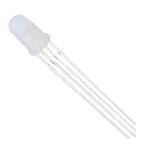
An RGB LED is three tiny LEDs, red, green and blue, under one frosted dome. Your eye can't see them apart, so it adds their light together: full red with a little green looks orange, red with blue looks purple. Set each one's brightness from code and you can make almost any color.
This mood lamp fades smoothly from color to color and names each one on a small OLED screen. The code passed its test in our simulator; below, it's explained line by line, with the color math laid out.
What you'll build and learn
The LED glides through red, orange, yellow, green, blue and purple, holding each for a moment, while the screen shows the name of the color it's heading to. You'll learn:
- PWM brightness with
analogWrite(), a value from 0 to 255 on the pins marked ~: PWM. - Color mixing on a common-cathode RGB LED.
- A table of colors in a two-dimensional array: arrays.
- Fading by stepping every channel from one color to the next.
- Text on an OLED with U8g2.
Run it: The mood lamp, running · The finished build in the CraftingTable simulator: the same parts, wiring and code as this page.
Parts
| Part | How many | Notes |
|---|---|---|
| HERO Board | 1 | Uno-compatible, ATmega328P |
| RGB LED, common cathode | 1 | 4 legs: red, common (the longest), green, blue |
| 220 Ω resistors | 3 | One per color leg, none on the common |
| OLED screen, 128x64, SH1106, I2C | 1 | 4 pins: GND, VCC, SCL, SDA |
| Breadboard | 1 | |
| Jumper wires | 9 |
30 Days Lost in Space includes all of it, and its first color mixing is Day 8. Cogsworth City has an RGB LED too, for its twelfth night, and the 37-in-1 Sensor Kit has two RGB modules, the KY-016 and the tiny surface-mount KY-009.
Wiring
| From | Through | To |
|---|---|---|
| RGB LED red leg | 220 Ω resistor | D9 |
| RGB LED common leg (longest) | Breadboard GND rail | |
| RGB LED green leg | 220 Ω resistor | D10 |
| RGB LED blue leg | 220 Ω resistor | D11 |
| HERO Board GND | GND rail | |
| OLED SDA | A4 | |
| OLED SCL | A5 | |
| OLED VCC | 5V | |
| OLED GND | GND rail |
Seat the LED's four legs in four rows side by side, in the order they come out of it: red, common, green, blue. Turned round, red and blue trade places, and the sketch asks for red while you see blue. All three color pins are PWM pins, marked ~ on the board. That matters: on a pin without PWM, analogWrite() is either fully on or fully off, and the fades turn into jumps.
Each color leg gets its own resistor. One shared resistor on the common leg would let red, which needs the least voltage to light, take most of the current, and every mix would lean toward orange.
The code
Install U8g2 by olikraus from the Library Manager in the Arduino IDE, then upload.
// Mood lamp: the RGB LED fades through the colors, and the screen names each one.
#include <U8g2lib.h>
#include <Wire.h>

// The page buffer (_1_) draws the screen in strips from 128 bytes of RAM; the whole frame (_F_) would take 1,024 of
// the board's 2,048 and leave too little for everything else.
U8G2_SH1106_128X64_NONAME_1_HW_I2C u8g2(U8G2_R0);

const int RED_PIN = 9;     // PWM pins, so each color can dim
const int GREEN_PIN = 10;
const int BLUE_PIN = 11;

const int COUNT = 6;
const char* NAMES[COUNT] = {"Red", "Orange", "Yellow", "Green", "Blue", "Purple"};
const byte COLORS[COUNT][3] = {
  {255, 0, 0}, {255, 60, 0}, {255, 160, 0}, {0, 255, 0}, {0, 0, 255}, {150, 0, 255}
};

int current = 0;

void showName(const char* name) {
  u8g2.firstPage();
  do {   // the screen is drawn in 8 strips: this runs once for each
    u8g2.setFont(u8g2_font_ncenB14_tr);
    u8g2.drawStr(8, 40, name);
  } while (u8g2.nextPage());
}

void setColor(int r, int g, int b) {
  analogWrite(RED_PIN, r);
  analogWrite(GREEN_PIN, g);
  analogWrite(BLUE_PIN, b);
}

void setup() {
  u8g2.begin();
  Serial.begin(9600);
}

void loop() {
  int next = (current + 1) % COUNT;
  showName(NAMES[next]);
  Serial.println(NAMES[next]);

  // Fade from this color to the next in 20 small steps.
  for (int step = 0; step <= 20; step++) {
    int r = COLORS[current][0] + (COLORS[next][0] - COLORS[current][0]) * step / 20;
    int g = COLORS[current][1] + (COLORS[next][1] - COLORS[current][1]) * step / 20;
    int b = COLORS[current][2] + (COLORS[next][2] - COLORS[current][2]) * step / 20;
    setColor(r, g, b);
    delay(25);
  }
  current = next;
  delay(800);   // how long each color stays
}How the code works
The color table
COLORS is a table with one row per color and three columns: red, green and blue, each 0 to 255. {255, 60, 0} is full red with a little green, which reads as orange; {150, 0, 255} is blue with some red, which reads as purple. NAMES holds the matching words in the same order. To add a color, add a row to each and raise COUNT.
setColor()
analogWrite(pin, value) switches the pin on and off about 490 times a second, and value sets how much of each cycle it stays on: 64 is a quarter of the time, 255 all of it. Your eye averages the flicker into brightness. setColor() does that for all three legs at once.
The fade
Each pass of loop() picks the next color and walks there in 21 steps, as step runs from 0 to 20. At every step each channel moves the same share of the way: start + (end - start) * step / 20. At step 0 that's the old color, at step 20 exactly the new one. With 25 ms per step, a fade takes about half a second, and the color then holds for 800 ms.
The multiplication comes before the division on purpose. Whole-number math drops fractions, so dividing first would lose a little at every step: from 255 down to 0, (0 - 255) / 20 * step stops at 15 instead of 0. Multiplying first keeps the remainder until the very end.
The name on the screen
showName() draws the next color's name in a 14-pixel bold font before the fade begins, and Serial prints it too. The screen uses U8g2's page buffer, which draws in eight strips from 128 bytes, so the whole sketch keeps 905 of the board's 2,048 bytes of RAM in use.
Try it without parts
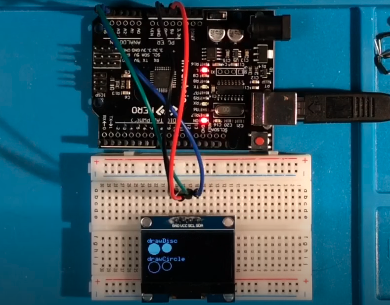
The RGB LED and the OLED are both parts in the free browser simulator. Wire them as in the table, paste the sketch and press Run: the LED on screen shows the mixed color as it fades, so you can tune your palette before you build.
Make it yours
- Your own palette. Change the rows of
COLORS.{0, 255, 255}is cyan,{255, 0, 255}magenta,{255, 255, 255}white, which often looks a little blue or pink because the three tiny LEDs aren't perfectly matched; trim the strongest channel until it looks right. - Slower, calmer fades. Raise the 25 ms step delay to 100 for a two-second fade, and the 800 ms hold to let each color linger.
- Pick colors with a knob. Let a rotary encoder move through
COLORSinstead of the timer. The encoder menu shows how to read one. - Add a beep, but move blue first.
tone()borrows Timer2, the same timer that runs PWM on pin 11, so while a note plays the blue channel misbehaves. Move blue's wire andBLUE_PINto pin 5 or 6, which run on a different timer, before you addtone().
Common problems
- Red and blue are swapped. The LED is turned round. The longest leg is the common; red sits on one side of it, green and blue on the other.
- No color lights at all. The common leg doesn't reach the GND rail, or the rail isn't joined to the board's GND.
- One color is missing. That leg's resistor or pin wire is one row off, or on the wrong pin.
- The colors are inverted, cyan when you asked for red. You have a common-anode LED: its common leg goes to 5V instead of GND, and every value must be flipped with
255 - value. - The fades jump instead of gliding. A color wire is on a pin without ~. Only 3, 5, 6, 9, 10 and 11 can dim.
30 Days Lost in Space: The HERO Board, the RGB LED, the OLED screen and the resistors, with filmed lessons that start color mixing on Day 8 and use it as a status light later.
Cogsworth City: HERO Starter Kit: The HERO Board, an RGB LED, LEDs, push buttons and two light sensors, with twenty nights of lessons in a steampunk story.
Questions
What resistor should I use for an RGB LED?
220 Ω on each color leg works well on the HERO Board's 5 volts; 330 Ω is a little dimmer and also fine. Put one on each color leg and none on the common.
Is my RGB LED common cathode or common anode?
Wire the longest leg to GND and one color leg to 5V through a 220 Ω resistor. If it lights, it's common cathode, the kind this sketch expects. If not, try the long leg on 5V and the color leg to GND through the resistor: if that lights, it's common anode.
How many colors can an RGB LED make?
With 256 levels on each of three channels, about 16.7 million combinations, though your eye can't tell many of them apart, especially near full brightness.
Why does analogWrite only dim some pins?
Only pins with PWM hardware can switch fast enough to dim: 3, 5, 6, 9, 10 and 11 on the HERO Board, marked ~. On any other pin, analogWrite() just turns the pin fully on or fully off.