Build a traffic light with three LEDs
Updated
A traffic light is the classic first sequence: three LEDs, three pins, and a loop that walks through red, green and yellow forever. It looks simple, and it is, but it holds the idea behind every machine that runs in steps, from a washing machine to the enemy in a video game.
This page builds it on the HERO Board with the code that passed its test in our simulator, explains each line, and then shows the three upgrades that turn it from a blinking toy into a real controller.
What you'll build and learn
Red lights for a second and a half, then green for a second and a half, then yellow for half a second, and back to red. Building it teaches:
- Digital outputs.
pinMode()anddigitalWrite()switch a pin between 0 and 5 volts: digital I/O. - Why every LED needs a resistor, and which leg goes where: the LED and resistor articles.
- Functions. One small function sets all three lights at once, so each step of the sequence is a single readable line: functions.
- Timed steps with
delay(), and the point where a bigger project has to move to millis().
Run it: The traffic light, running · The finished build in the CraftingTable simulator: the same parts, wiring and code as this page.
Parts
| Part | How many | Notes |
|---|---|---|
| HERO Board | 1 | Uno-compatible, ATmega328P |
| Breadboard | 1 | Any size |
| LEDs | 3 | Red, yellow and green |
| 220 Ω resistors | 3 | One per LED. On the kit's blue resistors: red, red, black, black, brown |
| Jumper wires | 7 | Three from the pins, three to ground, one for the board's GND |
| USB cable | 1 | Power and upload |
30 Days Lost in Space has all of it: its ten LEDs include two each of red, yellow and green, and its resistors include 220 Ω. Cogsworth City has the HERO Board, LEDs, resistors and a breadboard too, and its third night lights three lamps in order, the same idea in a story.
Wiring
Each light is the same small loop: pin, resistor, LED, ground. Build one, then copy it twice.
| From | Through | To |
|---|---|---|
| HERO Board GND | The breadboard's GND rail | |
| D10 | 220 Ω resistor | Red LED, long leg |
| Red LED, short leg | GND rail | |
| D11 | 220 Ω resistor | Yellow LED, long leg |
| Yellow LED, short leg | GND rail | |
| D12 | 220 Ω resistor | Green LED, long leg |
| Green LED, short leg | GND rail |
The long leg is the anode (+); the short leg, beside the flat spot on the LED's rim, is the cathode.
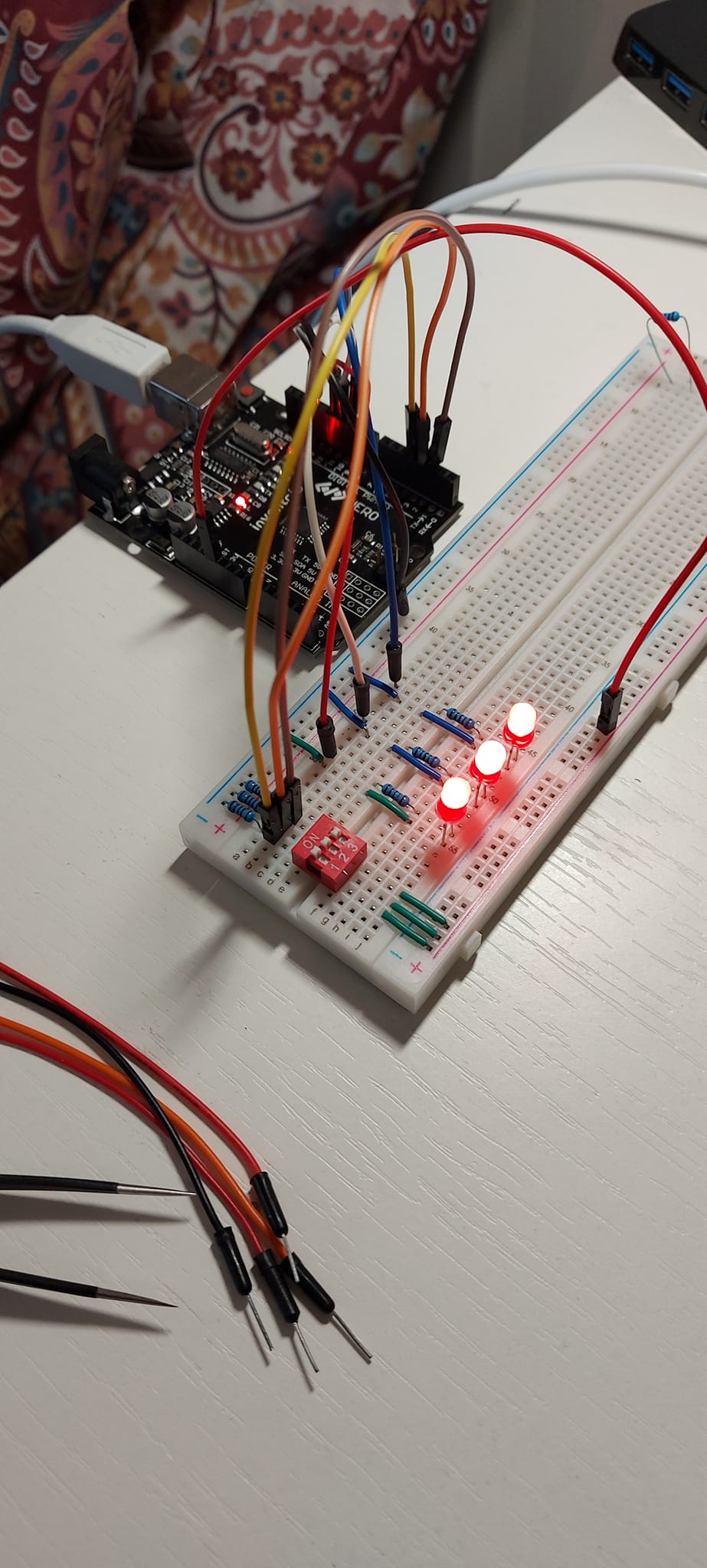
On a breadboard, two parts connect when they share one of the five-hole rows. Put the jumper from D10 and one resistor leg in one row, the resistor's other leg and the red LED's long leg in a second row, and the LED's short leg in a third row with a jumper to the GND rail. Give each light its own rows. Pins 10, 11 and 12 are the same three that Day 4 of 30 Days Lost in Space uses for its cabin, storage and cockpit lights. The photo at the top of this page is a builder's Day 4.
The code
No libraries to install. Paste this into the Arduino IDE and upload it.
// Traffic light: red, then green, then yellow, then red again.
const int RED = 10;
const int YELLOW = 11;
const int GREEN = 12;

void show(int red, int yellow, int green) {
  digitalWrite(RED, red);
  digitalWrite(YELLOW, yellow);
  digitalWrite(GREEN, green);
}

void setup() {
  pinMode(RED, OUTPUT);
  pinMode(YELLOW, OUTPUT);
  pinMode(GREEN, OUTPUT);
}

void loop() {
  show(HIGH, LOW, LOW);   // stop
  delay(1500);
  show(LOW, LOW, HIGH);   // go
  delay(1500);
  show(LOW, HIGH, LOW);   // slow down
  delay(500);
}How the code works
Names for the pins
const int RED = 10; gives each pin a name. The rest of the sketch never says 10 again, so moving the red LED to another pin is a one-line change, and every line reads as what it means.
One function for all three lights
show(red, yellow, green) sets all three pins in one call. HIGH puts 5 volts on a pin and lights its LED; LOW puts 0 volts and turns it off. Because the function always sets all three, no step can leave a light on by accident. That's the habit behind every good sequence: each step states the whole picture, not just what changed.
The sequence
setup() runs once and makes the three pins outputs. loop() is three steps: stop for 1,500 ms, go for 1,500 ms, slow down for 500 ms. When loop() reaches its end it starts again from the top, so the light runs until you unplug it. The order is red, green, yellow, red, as most lights in North America run. In the UK, red and amber show together before green; add that step yourself with show(HIGH, HIGH, LOW);.
Try it without parts
Build it first in the free browser simulator: drop a HERO Board, a breadboard, three LEDs and three resistors on the bench, wire them as in the table and press Run. The simulator lights each LED when current actually flows through it, so a backwards LED stays dark there too.
Make it yours
- Real timings. A real light holds green for far longer than a second and a half. Change the three delays and the sequence stays the same.
- A crossroads. Two lights, six LEDs: whenever one shows green, the other shows red. The 30 Days kit's two LEDs of each color are exactly enough. Put the second light on three free pins (D5, D6 and D7 work) and give
show()six arguments. - A crossing button. With
delay(), the board only notices a button between steps, so a press during a long green is missed. The fix is to dropdelay(), time each step with millis() and keep the current step in a variable: a state machine. Then the board can check the button thousands of times a second. Cogsworth City comes with six push buttons; debouncing explains how to read one cleanly.
Common problems
- One LED stays dark. It's in backwards. The long leg goes toward the resistor and the pin, the short leg toward ground. Turned round, an LED doesn't break, it just doesn't light. More checks: My LED won't turn on.
- Nothing lights at all. The GND rail isn't joined to the board's GND, so no LED has a way back. One jumper fixes all three.
- An LED is very dim. The sketch is missing its
pinMode(pin, OUTPUT)line, or a 10 kΩ resistor went in where a 220 Ω belongs (on the kit's blue resistors, 10 kΩ reads brown, black, black, red, brown). - The lights come on in the wrong order. Two pin wires are swapped at the board. Follow each wire from its LED's row to its pin.
- An LED flashed once and never again. It was wired without its resistor and burned out. Replace it and keep a 220 Ω in every loop.
30 Days Lost in Space: The HERO Board, ten LEDs, resistors, a breadboard and jumper wires, with filmed lessons that start from one blinking light and end flying a ship home.
Cogsworth City: HERO Starter Kit: The HERO Board, LEDs, an RGB LED, six push buttons, two light sensors and resistors, with twenty nights of lessons that start from the board's own light.
Questions
What resistor do I need for a traffic light LED?
220 Ω on each LED is right for the HERO Board's 5 volts. It lets about 14 mA through a red LED, bright and safe. 150 Ω is the lowest you should go; anything higher, up to 1 kΩ, still works and is just dimmer.
Can the three LEDs share one resistor?
In this sequence only one LED is lit at a time, so one resistor on the shared ground would work. Give each its own anyway: the moment two light together, as in a UK red and amber or a crossroads, red needs less voltage than green and takes most of the current.
Which pins can I use for the LEDs?
Any of D2 to D13 or A0 to A5 can switch an LED on and off. Avoid D0 and D1, which carry the USB serial line to your computer. Change the pin numbers at the top of the sketch to match your wiring.
Why does my traffic light miss button presses?
Because delay() stops the board from doing anything else, including reading a button. Time each step with millis() instead and check the button on every pass of loop().