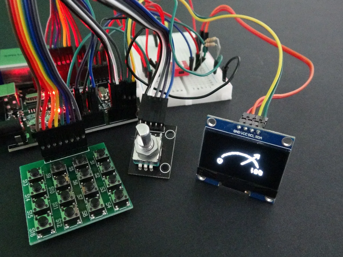
Build a rotary encoder menu on an OLED screen
Updated
Every gadget with a screen and a knob, from a 3D printer to a car stereo, runs the same menu underneath: a list, a marker, a knob that moves the marker and a press that picks. Build it once and every project after it can have settings.
This one puts four items on a 128x64 OLED screen, moves a > marker as you turn a rotary encoder, and reports your pick when you press the knob in. The code passed its test in our simulator: two clicks clockwise and a press printed Picked Timer.
What you'll build and learn
- Reading a rotary encoder, the knob that turns forever and reports each click and its direction: rotary encoder.
- Interrupts. The chip drops what it's doing the instant the knob moves, so no click is lost while the screen redraws.
- Drawing a list on the SH1106 screen with U8g2: U8g2 and OLED display.
- An array of text, and wrapping a position round the end of a list in both directions.
- Edge detection on the knob's push button: act once per press, not once per pass of the loop.
Run it: The encoder menu, running · The finished build in the CraftingTable simulator: the same parts, wiring and code as this page.
Parts
| Part | How many | Notes |
|---|---|---|
| HERO Board | 1 | Uno-compatible, ATmega328P |
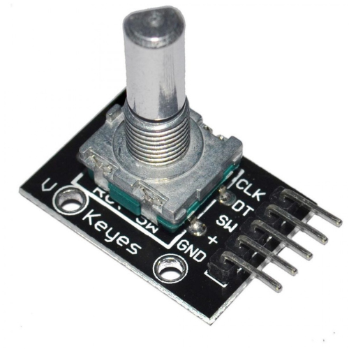
| Rotary encoder module | 1 | 5 pins: CLK, DT, SW, +, GND |
| OLED screen, 128x64, SH1106, I2C | 1 | 4 pins: GND, VCC, SCL, SDA |
| Breadboard | 1 | For the shared 5V and GND rails |
| Jumper wires | 11 |
30 Days Lost in Space includes all of them; its encoder has 20 clicks per full turn. Pandora's Box has a rotary encoder too, and the 37-in-1 Sensor Kit has the same kind of knob as its KY-040 module.
Wiring
| Part pin | Goes to | Notes |
|---|---|---|
| HERO Board 5V | Breadboard 5V rail | |
| HERO Board GND | Breadboard GND rail | |
| Encoder CLK | D2 | Pin 2 can trigger an interrupt |
| Encoder DT | D3 | Read to tell the direction |
| Encoder SW | D4 | The push button: LOW while pressed |
| Encoder + | 5V rail | Power |
| Encoder GND | GND rail | |
| OLED SDA | A4 | I2C data |
| OLED SCL | A5 | I2C clock |
| OLED VCC | 5V rail | Power |
| OLED GND | GND rail |
On the HERO Board only pins 2 and 3 can trigger an interrupt, which is why CLK goes to 2. The screen's pins are fixed too: on this board, I2C data is always A4 and the clock always A5. Go by the labels printed on the screen's header, not the order in a picture; the kit's screen reads GND, VCC, SCL, SDA from the left, and some screens put VCC first.
The code
Install U8g2 by olikraus from the Library Manager in the Arduino IDE, then upload this sketch and open the Serial Monitor at 9600 baud.
// Menu: turn the knob to move the marker, press it to pick. The screen shows the list; Serial says what was picked.
// The knob is counted in an interrupt: redrawing the screen takes a few milliseconds, and a fast turn would be missed
// if loop() had to catch every click itself.
#include <U8g2lib.h>
#include <Wire.h>

// The page buffer (_1_) draws the screen in strips from 128 bytes of RAM; the whole frame (_F_) would take 1,024 of
// the board's 2,048 and leave too little for everything else.
U8G2_SH1106_128X64_NONAME_1_HW_I2C u8g2(U8G2_R0);

const int CLK_PIN = 2;   // pin 2 can wake an interrupt
const int DT_PIN = 3;
const int SW_PIN = 4;

const char* ITEMS[] = { "Lights", "Sound", "Timer", "About" };
const int ITEM_COUNT = 4;
volatile int clicks = 0;   // changed inside the interrupt, so volatile
int selected = 0;
int lastSw = HIGH;

void onClick() {   // runs the moment CLK falls: one click of the knob
  if (digitalRead(DT_PIN) == HIGH) clicks++;
  else clicks--;
}

void drawMenu(const char* picked) {
  u8g2.firstPage();
  do {   // the screen is drawn in 8 strips: this runs once for each
    u8g2.setFont(u8g2_font_6x10_tr);
    for (int i = 0; i < ITEM_COUNT; i++) {
      int y = 12 + i * 12;
      if (i == selected) u8g2.drawStr(0, y, ">");
      u8g2.drawStr(12, y, ITEMS[i]);
    }
    if (picked) {
      u8g2.drawStr(70, 12, "Picked:");
      u8g2.drawStr(70, 24, picked);
    }
  } while (u8g2.nextPage());
}

void setup() {
  pinMode(CLK_PIN, INPUT_PULLUP);
  pinMode(DT_PIN, INPUT_PULLUP);
  pinMode(SW_PIN, INPUT_PULLUP);
  attachInterrupt(digitalPinToInterrupt(CLK_PIN), onClick, FALLING);
  Serial.begin(9600);
  u8g2.begin();
  drawMenu(nullptr);
}

void loop() {
  noInterrupts();   // take the clicks counted so far, without the interrupt changing them halfway
  int turned = clicks;
  clicks = 0;
  interrupts();
  if (turned != 0) {
    selected = ((selected + turned) % ITEM_COUNT + ITEM_COUNT) % ITEM_COUNT;
    drawMenu(nullptr);
  }

  int sw = digitalRead(SW_PIN);
  if (sw == LOW && lastSw == HIGH) {   // the knob pressed in
    Serial.print("Picked ");
    Serial.println(ITEMS[selected]);
    drawMenu(ITEMS[selected]);
  }
  lastSw = sw;
}How the code works
Counting clicks in an interrupt
attachInterrupt(digitalPinToInterrupt(CLK_PIN), onClick, FALLING) tells the chip: whenever pin 2 falls from HIGH to LOW, stop and run onClick(). Each click of the knob makes CLK fall once. Inside, DT says which way you turned, because the encoder's two signals are offset: turning one way, DT is still HIGH when CLK falls; the other way, it's already LOW. clicks goes up or down by one. It's marked volatile because it changes outside the normal flow of the program, so the compiler must read it fresh every time.
Taking the clicks safely
clicks is an int, two bytes, and the HERO Board's chip reads it one byte at a time. If an interrupt landed between the two bytes, loop() could read half an old number and half a new one. So loop() turns interrupts off for the two lines that copy and clear it, then straight back on. A click in those few microseconds isn't lost: it waits, and is counted the moment interrupts return.
Wrapping round the list
((selected + turned) % ITEM_COUNT + ITEM_COUNT) % ITEM_COUNT keeps the marker on the list in both directions. In C++, % of a negative number is negative (-1 % 4 is -1), so adding ITEM_COUNT and taking % again turns -1 into 3: turn back past Lights and you land on About.
The button
SW uses INPUT_PULLUP, so it reads HIGH until you push the knob in and LOW while you hold it. Comparing with lastSw catches the one moment it changes from HIGH to LOW, so a press picks once however long you hold it.
Drawing the menu
drawMenu() writes the four items 12 pixels apart in a small 6x10 font, puts > beside the selected one, and adds Picked: on the right after a press. The screen only redraws when something changes, which keeps the loop free to watch the button. Like every OLED sketch in these projects, it uses U8g2's page buffer (_1_), which draws in eight strips from 128 bytes, so the whole sketch keeps 899 of the board's 2,048 bytes of RAM in use.
Try it without parts
The encoder and the OLED are both parts in the free browser simulator. Wire them to a HERO Board as in the table, paste the sketch and press Run, then turn and press the knob on screen and watch the marker move.
Make it yours
- Make the items do something. Replace the Serial print with a switch/case on
selected: case 0 toggles a light, case 1 plays a beep, and so on. - A value screen. Picking Timer could open a second screen where the knob sets a number and a press saves it. Keep which screen you're on in a variable, and you've built a state machine. The countdown timer is the same knob setting seconds.
- More items than fit. At this spacing five lines fit on the screen. For a longer list, draw only the items around
selectedand slide that window as the marker moves.
Common problems
- The marker moves the wrong way. CLK and DT are swapped at the board. Swap the two wires, or swap
clicks++andclicks--inonClick(). - It jumps two items for one click, or skips. The knob's contacts bounce, or a jumper on its pins is loose. Push the jumpers firmly on and turn slowly. If it still double-counts, the BasicEncoder library filters the bounce for you.
- Turning does nothing. The encoder has no power (+ to 5V, GND to GND), or CLK isn't on pin 2, the interrupt pin the sketch names.
- Pressing does nothing. SW isn't on D4. The press only counts the moment it goes down, so hold-and-release is one pick.
- The screen is blank or shifted. SDA and SCL swapped, power swapped, or an SSD1306 screen that needs
SSD1306in place ofSH1106in the constructor. The blank OLED checklist has the rest.
30 Days Lost in Space: The HERO Board, the rotary encoder and the OLED screen, a keypad and a 4-digit display, with filmed lessons that take the screen from its first text to sprites you draw yourself.
Questions
Why use an interrupt for a rotary encoder?
Clicks happen whenever your hand moves, not when the loop is ready. Redrawing an OLED takes a few milliseconds, and a click that comes and goes in that time is lost. An interrupt counts it the instant it happens.
Which pins can the encoder use on the HERO Board?
For attachInterrupt, CLK has to be on pin 2 or 3, the only interrupt pins on the HERO Board. DT and SW can go on any digital pin; change DT_PIN and SW_PIN to match.
How many menu items fit on a 128x64 OLED?
Five, with this 6x10 font spaced 12 pixels apart. A smaller font or tighter spacing fits more, or you can scroll a window through a longer list.
Does this work with an SSD1306 OLED?
Yes. Change SH1106 to SSD1306 in the constructor line and leave everything else as it is.