KY-016 RGB LED module: pinout, wiring and code
Updated
The KY-016 is a full-color light you can wire in a minute: a clear 5 mm RGB LED with its three resistors already on the board. Four wires to three PWM pins and ground, and it can show any color you can describe in three numbers.
That's why it's the RGB module to start with. Here's what the parts on the board do, how the SensorKit walkthrough wires it, a line-by-line look at its code (including two traps worth knowing), and a cleaner sketch for setting exact colors.
What the resistors are doing
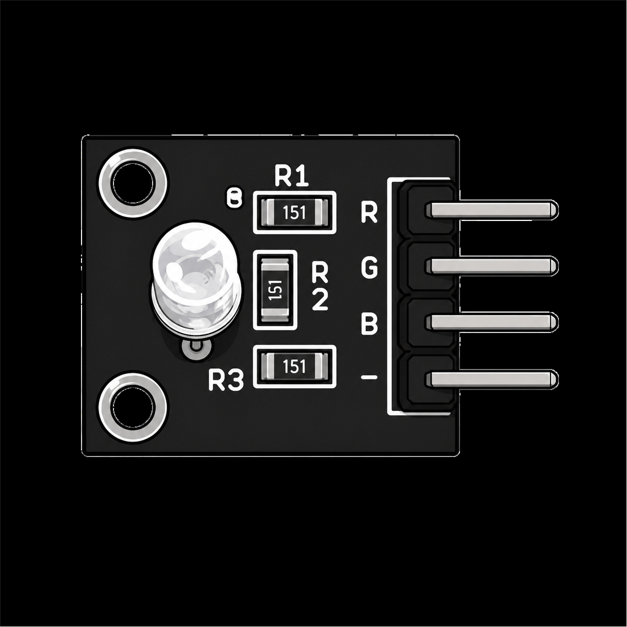
Look at the board and you'll see the LED, three small resistors labelled R1, R2 and R3, and a header printed R, G, B and −. Each resistor is marked 151: 15 followed by one zero, so 150 ohms. One sits in line with each color, limiting the current so the LED and your board's pins stay safe. That's the whole reason you can connect the KY-016 straight to the pins, where its flat cousin the KY-009 needs resistors added.
Inside the clear dome are three LED chips that share their negative leg, the − pin: a common cathode. Set a color pin HIGH and that chip lights. analogWrite() it anywhere from 0 to 255 and it glows at that strength. Mix them and your eye adds the light: red and green make yellow, green and blue make cyan, all three make white with a slight tint, because the three chips are never perfectly matched.
Wiring it the way the walkthrough does
| KY-016 pin | HERO Board pin |
|---|---|
| R | D11 |
| G | D9 |
| B | D10 |
| − | GND |
From the SensorKit lesson's code and walkthrough. Green and blue cross over: G goes to D9 and B to D10.
All three color pins must be PWM pins, marked ~ on the board, or you only get fully on and fully off. The HERO Board has six: 3, 5, 6, 9, 10 and 11, and the lesson uses the top three. If you later add a part that talks over the SPI bus (D10 to D13), move red and blue to 5 and 6.
The walkthrough's code, and two traps in it
int redpin = 11;   // red LED
int bluepin = 10;  // blue LED
int greenpin = 9;  // green LED
int val;

void setup() {
  pinMode(redpin, OUTPUT);
  pinMode(bluepin, OUTPUT);
  pinMode(greenpin, OUTPUT);
  Serial.begin(115200);
}

void loop() {
  for (val = 255; val > 0; val--) {
    analogWrite(redpin, val);
    analogWrite(bluepin, 255 - val);
    analogWrite(greenpin, constrain(128 - val, 0, 255));
    delay(10);
    Serial.println(val, DEC);
  }
  for (val = 0; val < 255; val++) {
    analogWrite(redpin, val);
    analogWrite(bluepin, 255 - val);
    analogWrite(greenpin, constrain(128 - val, 0, 255));
    delay(10);
    Serial.println(val, DEC);
  }
}The idea is a slow cross-fade. As val counts down from 255, red dims while blue brightens by the same amount, then the second loop runs it back. Each step waits 10 ms, so one sweep takes about two and a half seconds. Serial.println() prints val on every step; open the Serial Monitor at 115200 baud, as the walkthrough does, and you can watch the count that drives the colors.
- Every pin is named once.
setup()andloop()both useredpin,bluepinandgreenpin, so moving a color to another PWM pin means changing one line at the top. 128 - valgoes below zero for half of each sweep, andanalogWrite()only understands 0 to 255, so the sketch wraps it inconstrain(128 - val, 0, 255). Green glows in the middle of the sweep and rests at zero the rest of the time. constrain() has its own Help Center article.
Set an exact color
Most projects don't want a sweep. They want a particular color at a particular moment: green for ready, amber for wait, red for stop. A three-line function turns that into one call.
const int RED_PIN = 11;
const int GREEN_PIN = 9;
const int BLUE_PIN = 10;

void setColor(int red, int green, int blue) {
  analogWrite(RED_PIN, red);
  analogWrite(GREEN_PIN, green);
  analogWrite(BLUE_PIN, blue);
}

void setup() {
  pinMode(RED_PIN, OUTPUT);
  pinMode(GREEN_PIN, OUTPUT);
  pinMode(BLUE_PIN, OUTPUT);
}

void loop() {
  setColor(0, 255, 0);    // green
  delay(1000);
  setColor(255, 80, 0);   // amber
  delay(1000);
  setColor(255, 0, 0);    // red
  delay(1000);
}Tune mixed colors by eye. Brightness doesn't look linear (the jump from 0 to 50 looks bigger than the jump from 200 to 255), and no two LEDs match exactly, so 255, 80, 0 may need nudging before it reads as amber on yours. The RGB LED article has a table of starting mixes.
What to build with it
- A status light. Day 14 of 30 Days Lost in Space uses an RGB LED as a security panel's status: green while all is well, red for an alarm.
setColor()is all the code it takes. - A mood lamp that fades between colors and names each one, like the mood lamp example verified in the CraftingTable simulator.
- A one-LED traffic light: green, amber and red from the sketch above, with longer delays.
- A temperature color: read the KY-015 sensor from the same kit and slide from blue when it's cool to red when it's warm.
When it doesn't work
- Nothing lights. The − pin isn't on GND, or the module is turned round so − sits on a color wire.
- A color is stuck fully on or off. It's on a pin without PWM. Move it to one of 3, 5, 6, 9, 10 or 11.
- Changing a pin variable does nothing. You're running an older copy of the sketch that typed 11, 10 and 9 straight into
loop(). Use the variable names there too, as the current lesson code does. - Green jumps mid-fade. Same older copy:
128 - valwent negative. Wrap it inconstrain().
The KY-016 is one of the parts in the free browser simulator, so setColor() can be tried with no wiring. Watch it on the bench in the KY-016 walkthrough, and see the rest of the case in the 37-in-1 sensor kit guide.
37-in-1 Sensor Kit: The KY-016 and 36 more modules in a latching case, with the free SensorKit course: 31 filmed walkthroughs and their code.
HERO Board: The Uno-compatible board every SensorKit walkthrough is filmed on, with six PWM pins for color mixing.
Questions
Does the KY-016 need resistors?
No. Its board carries three 150 ohm resistors (marked 151), one for each color, so you can wire R, G and B straight to your board's pins.
Is the KY-016 common cathode or common anode?
Common cathode. The − pin is the shared ground, and a color turns on when its pin goes HIGH. analogWrite() values closer to 255 make it brighter.
Which pins can the KY-016 use?
Any three PWM pins. On the HERO Board those are 3, 5, 6, 9, 10 and 11, marked ~. The SensorKit lesson uses 11 for red, 9 for green and 10 for blue.
What's the difference between the KY-016 and the KY-009?
The KY-016 is a 5 mm LED with resistors on the board. The KY-009 is a flat surface-mount LED with none, so it needs three resistors added. The code is the same.