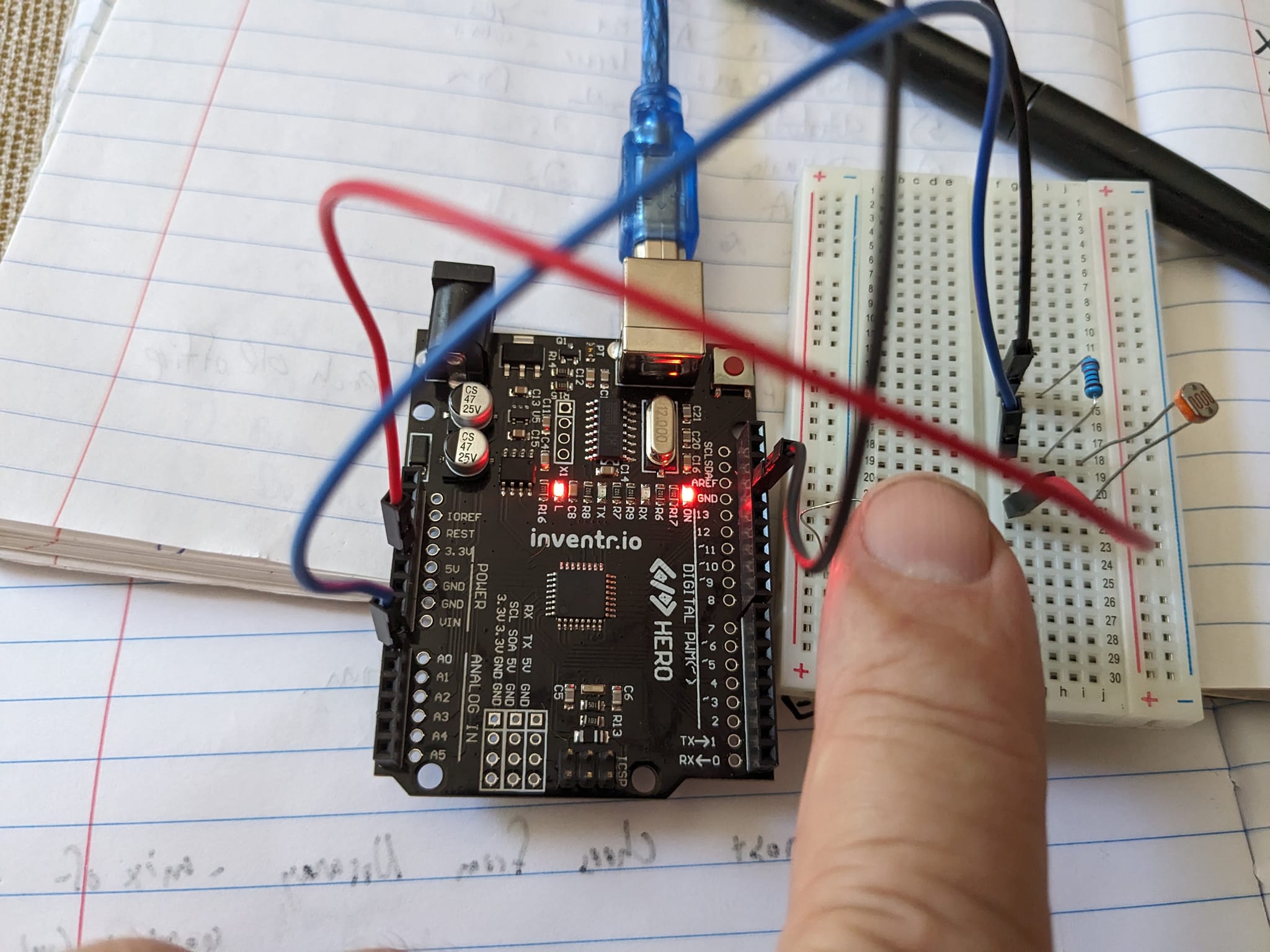
Build a night light that turns on in the dark
Updated
A night light is the first build where your board makes a decision on its own. A photoresistor tells it how bright the room is, and when the number drops below a line you chose, the LED comes on. Nobody presses anything.
Below are the parts, the wiring of the voltage divider that makes the sensor readable, and the code that passed its test in our simulator. Then a second build turns the same sensor into a light meter, with a percentage and a live graph on an OLED screen.
What you'll build and learn
Cover the sensor, or turn the room lights off, and the LED switches on. Let the light back in and it switches off. You'll learn:
- Reading an analog sensor.
analogRead()turns 0 to 5 volts into a number from 0 to 1023: analog input. - The voltage divider, and why the photoresistor needs a 10 kΩ partner before the board can read it: voltage dividers and the photoresistor article have the math.
- A threshold with if/else.
- Calibrating with the Serial Monitor: measuring your own room before you choose the number.
Run it: The night light, running · The finished build in the CraftingTable simulator: the same parts, wiring and code as this page.
Parts
| Part | How many | Notes |
|---|---|---|
| HERO Board | 1 | Uno-compatible, ATmega328P |
| Breadboard | 1 | Any size |
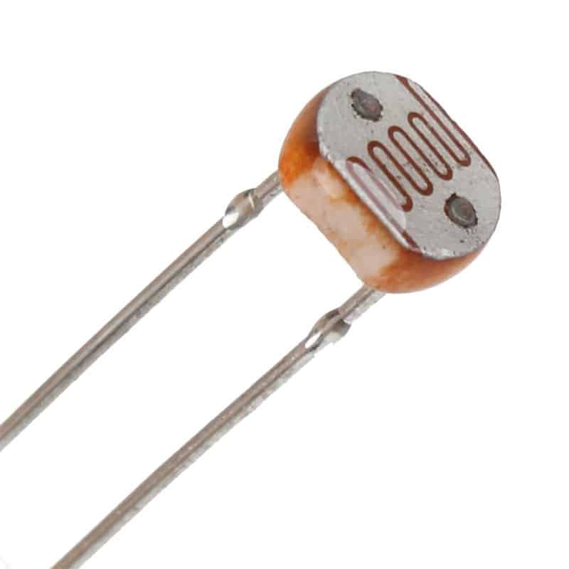
| Photoresistor (LDR) | 1 | No polarity: either way round works |
| 10 kΩ resistor | 1 | The fixed half of the divider |
| 220 Ω resistor | 1 | For the LED |
| LED | 1 | Any color; yellow looks like a lamp |
| Jumper wires | 7 |
30 Days Lost in Space and Cogsworth City both include everything here, and Cogsworth City comes with two photoresistors. The same sensor is the lander's solar panel on Day 6 of 30 Days, and the eye that spots the searchlight on Night 6 of Cogsworth City.
Wiring
The board can't measure resistance, only voltage. So the photoresistor and a 10 kΩ resistor are joined end to end between 5V and GND, and A0 reads the point where they meet. More light lowers the photoresistor's resistance, which pulls that point toward 5 volts, so the reading rises with the light.
| From | To | Why |
|---|---|---|
| HERO Board 5V | Breadboard 5V rail | Power for the divider |
| HERO Board GND | Breadboard GND rail | Shared ground |
| Photoresistor, one leg | 5V rail | Top of the divider |
| Photoresistor, other leg | A0, and one leg of the 10 kΩ resistor, all in one row | The middle point A0 reads |
| 10 kΩ resistor, other leg | GND rail | Bottom of the divider |
| D9 | 220 Ω resistor, then the LED's long leg | The lamp |
| LED, short leg | GND rail | The lamp's way back |
The row that matters most is the middle one: the photoresistor's second leg, the A0 wire and the 10 kΩ all share one five-hole row. Keep the two photoresistor legs in different rows, or the sensor is shorted out and the number never moves.
The code
// Night light: the LED on D9 comes on when the room gets dark.
// The light sensor and a 10k resistor make a divider on A0: more light, a higher reading.
const int SENSOR_PIN = A0;
const int LED_PIN = 9;
const int DARK = 200;   // below this reading it counts as dark (0 to 1023)

void setup() {
  pinMode(LED_PIN, OUTPUT);
  Serial.begin(9600);
}

void loop() {
  int light = analogRead(SENSOR_PIN);
  if (light < DARK) {
    digitalWrite(LED_PIN, HIGH);
  } else {
    digitalWrite(LED_PIN, LOW);
  }
  Serial.println(light);
  delay(200);
}How the code works
Five times a second, analogRead(SENSOR_PIN) measures the divider and returns a number from 0 to 1023, higher in brighter light. DARK = 200 is the line. Below it, digitalWrite(LED_PIN, HIGH) turns the lamp on; at 200 or above, LOW turns it off. The sketch also prints every reading, which is how you set that line for your own room.
Choose your threshold
Upload the sketch, open the Serial Monitor at 9600 baud and watch the numbers. Note the reading with the lights on, then cover the sensor or switch the lights off and note it again. Pick a value between the two, nearer the dark one, and put it in DARK. Every photoresistor and every room differs, but as a rough guide indoor light reads around 400 to 700, a dim room 100 to 300 and a covered sensor under 50.
Stop the flicker at dusk
When the room sits right at the line, small changes flip the LED on and off. The cure is a gap between the on point and the off point, called hysteresis. Replace the if/else with these two lines and the LED holds its state anywhere between 200 and 260:
if (light < DARK) digitalWrite(LED_PIN, HIGH);
else if (light > DARK + 60) digitalWrite(LED_PIN, LOW);Level up: a light meter on an OLED screen
Keep the whole circuit and add the OLED screen: SDA to A4, SCL to A5, VCC to the 5V rail and GND to the GND rail. Install U8g2 by olikraus from the Library Manager. This sketch shows the light as a percentage with a scrolling graph of the last 64 readings, and dims the LED smoothly instead of switching it: the darker the room, the brighter it glows.
// Light meter: how bright the room is, as a number and a graph on the screen.
// The darker it gets, the brighter the LED glows, like a night light.
#include <U8g2lib.h>
#include <Wire.h>

// The page buffer (_1_) draws the screen in strips from 128 bytes of RAM; the whole frame (_F_) would take 1,024 of
// the board's 2,048 and leave too little for everything else.
U8G2_SH1106_128X64_NONAME_1_HW_I2C u8g2(U8G2_R0);

const int SENSOR_PIN = A0;   // photoresistor and 10k resistor meet here
const int LED_PIN = 9;       // a PWM pin, so the LED can dim

const int POINTS = 64;       // the graph shows the last 64 readings
byte history[POINTS];
int next = 0;

void setup() {
  pinMode(LED_PIN, OUTPUT);
  Serial.begin(9600);
  u8g2.begin();
}

void loop() {
  int raw = analogRead(SENSOR_PIN);           // 0 (dark) to 1023 (bright)
  int percent = map(raw, 0, 1023, 0, 100);

  // Night light: dark room, bright LED.
  analogWrite(LED_PIN, map(raw, 0, 1023, 255, 0));

  history[next] = map(raw, 0, 1023, 0, 40);   // graph height in pixels
  next = (next + 1) % POINTS;

  char line[20];
  sprintf(line, "Light: %d%%", percent);

  u8g2.firstPage();
  do {   // the screen is drawn in 8 strips: this runs once for each
    u8g2.setFont(u8g2_font_ncenB08_tr);
    u8g2.drawStr(0, 12, line);
    for (int i = 0; i < POINTS; i++) {
      int h = history[(next + i) % POINTS];
      u8g2.drawVLine(i * 2, 63 - h, h + 1);     // oldest on the left
    }
  } while (u8g2.nextPage());

  Serial.print("Light ");
  Serial.print(percent);
  Serial.println("%");
  delay(100);
}Three ideas carry it. map(raw, 0, 1023, 0, 100) rescales the reading to a percentage, and map(raw, 0, 1023, 255, 0) turns it upside down for the LED: see map(). analogWrite() dims the LED with PWM, switching it on and off about 490 times a second, which is why it sits on D9, a pin marked ~. And history is a ring buffer: each new reading overwrites the oldest, next moves on one place, and the drawing loop starts from next, so the oldest bar is on the left and the newest on the right.
The screen is drawn with U8g2's page buffer, eight strips from 128 bytes, which keeps the whole sketch to 923 of the board's 2,048 bytes of RAM. In sprintf, %% prints a single percent sign.
Try it without parts
Both builds run in the free browser simulator. The photoresistor there has a light-level slider, so you can test your threshold and your hysteresis gap without waiting for sunset.
Make it yours
- Fade instead of switch. The light meter's
analogWrite(LED_PIN, map(raw, 0, 1023, 255, 0));line works on its own in the night light, no screen needed. - A lid alarm. Swap the LED for a passive buzzer and flip the test, so it sounds while light gets in: open a box and it sings. tone() and noTone() start and stop the sound.
- Calibrate in code. Record the darkest and brightest readings you see, then
map()everything between them onto 0 to 100. Move to a new room and you recalibrate instead of rewriting.
Common problems
- The reading is stuck at 1023. The 10 kΩ isn't reaching the GND rail, so A0 only sees the 5 volts.
- The reading is stuck at 0. The photoresistor isn't fed from the 5V rail, or the board's 5V wire to the rail is missing.
- The numbers jump about at random. The A0 wire isn't in the row the sensor and the 10 kΩ share, so the pin is floating.
- The number is squeezed down near 0. A 220 Ω went in where the 10 kΩ belongs. On the kit's blue resistors, 10 kΩ reads brown, black, black, red, brown.
- It works backwards, on in the light. The photoresistor and the 10 kΩ have swapped places. With the sensor on the ground side, dark gives a high number. Swap them back, or change
<to>.
Cogsworth City: HERO Starter Kit: The HERO Board, two light sensors, LEDs, an RGB LED, push buttons and resistors, with twenty nights of lessons in a steampunk story.
30 Days Lost in Space: Everything for both builds on this page, the OLED screen included, plus a keypad, a 4-digit display and a buzzer, with filmed lessons from zero.
Questions
Why does a photoresistor need a 10k resistor?
The board's analog pins measure voltage, not resistance. A 10 kΩ resistor in series with the photoresistor makes a voltage divider, so the voltage at A0 rises and falls with the light, and analogRead() can read it.
What threshold should I use for a night light?
Measure your own room: print the readings, note them in normal light and in the dark, and choose a value between the two, nearer the dark one. As a rough guide a dim room reads 100 to 300 and a covered sensor under 50.
Which way round does a photoresistor go?
Either way. A photoresistor has no polarity. What matters is which side of the divider it's on: between 5V and A0, more light gives a higher reading.
Why does my night light flicker when it gets dark?
The light is hovering right at the threshold, so tiny changes flip the LED. Use two thresholds, a lower one to switch on and a higher one to switch off, as in the hysteresis lines above.