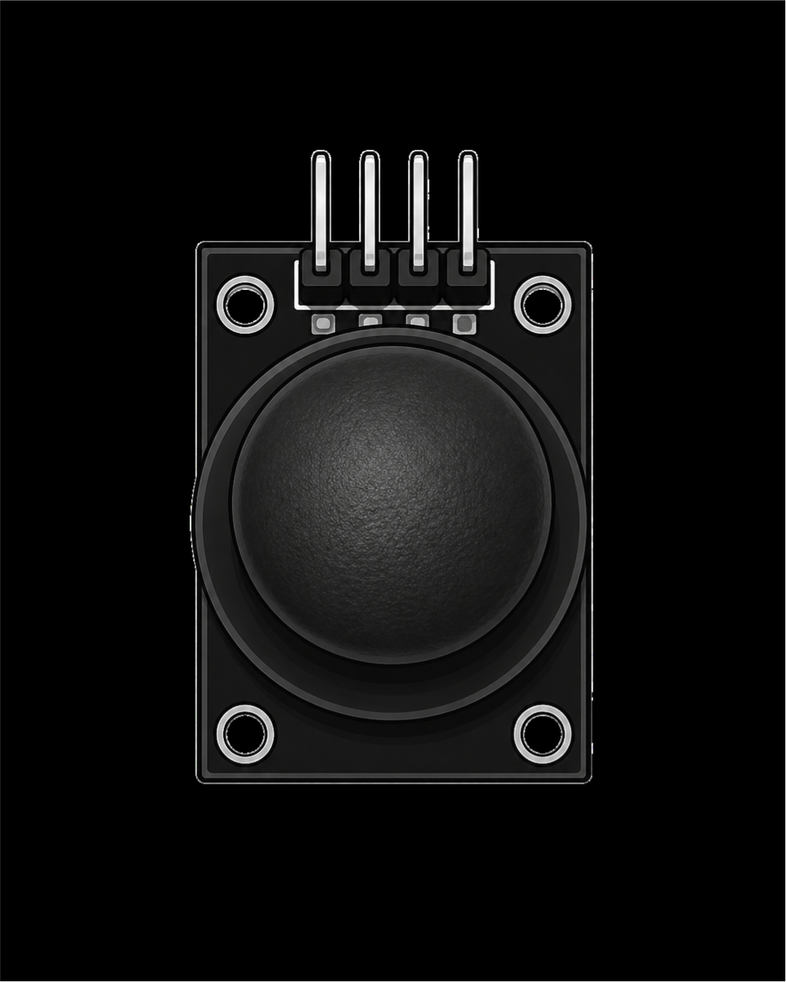
KY-023 joystick module: how it works, wiring and code
Updated
The KY-023 is the thumbstick from a game controller, on a board you can wire to a breadboard. Push it and it reports where it is on two axes. Press down on it and it clicks like a button. That's three readings from one part, and the SensorKit course reads all of them in about a dozen lines.
Here's what's under the cap, which of its five pins goes where, what the numbers mean when you open the Serial Monitor, and how to turn them into motion, from a servo that follows your thumb to a light you steer around a grid.
Two knobs and a button under one cap
The stick sits in a gimbal that turns two potentiometers, one for each axis. A potentiometer is a resistor with a sliding contact. Each one has 5 V across its ends, so the sliding contact outputs a voltage that follows the stick: near 0 V at one end of its travel, near 5 V at the other, about half in the middle. Those two outputs are VRx and VRy.
Press the stick straight down and it closes a small switch wired to SW. The switch joins SW to ground, so like the KY-004 button it reads LOW while pressed, as long as a pull-up holds it HIGH the rest of the time. Springs bring the stick back to the middle when you let go.
Wiring
| KY-023 pin | HERO Board pin | Reads as |
|---|---|---|
| GND | GND | Ground |
| +5V | 5V | Power for both potentiometers |
| VRx | A0 | Analog, the X axis |
| VRy | A1 | Analog, the Y axis |
| SW | D2 | Digital, the push switch |
From the SensorKit lesson's code and walkthrough, in the order the pins sit on the header.
VRx and VRy must go to analog pins, A0 to A5: only those can measure a voltage between 0 and 5 V. SW can go on any digital pin. As the walkthrough's instructor says, which analog pin gets which axis doesn't matter, as long as the code reads the same ones.
The code: read all three
const int SW_pin = 2;  // digital pin connected to the switch
const int X_pin = A0;  // analog pin connected to X
const int Y_pin = A1;  // analog pin connected to Y

void setup() {
  pinMode(SW_pin, INPUT);
  digitalWrite(SW_pin, HIGH);
  Serial.begin(115200);
}

void loop() {
  Serial.print("Switch:  ");
  Serial.print(digitalRead(SW_pin));
  Serial.print("\n");
  Serial.print("X-axis: ");
  Serial.print(analogRead(X_pin));
  Serial.print("\n");
  Serial.print("Y-axis: ");
  Serial.println(analogRead(Y_pin));
  Serial.print("\n\n");
  delay(500);
}pinMode(SW_pin, INPUT)followed bydigitalWrite(SW_pin, HIGH)is the older way of writingpinMode(SW_pin, INPUT_PULLUP). Writing HIGH to an input turns on the chip's internal pull-up resistor, so SW reads 1 at rest and 0 while you press.analogRead()turns the voltage on VRx and VRy into a number from 0 to 1023. With the stick centred, each axis reads around the middle, near 512.- The readings go to the Serial Monitor at 115200 baud, twice a second. In the Arduino IDE, open Tools, then Serial Monitor, set the speed to 115200, and push the stick around.
Making sense of the numbers
Push to one end of an axis and its reading heads for 0; push to the other end and it heads for 1023. Which way counts as "up" depends on how the board sits: in the walkthrough, lifting the stick moves the X reading, not Y, because of the way the module lies on the bench. Decide how you'll mount yours, then name the axes in your code to match.
You'll also notice that the resting value is rarely exactly 512, and it wobbles by a few counts. So treat a band around the centre as "not moving". That band is called a dead zone: something like if (abs(x - 512) < 50) x = 512; stops a game character drifting or a servo twitching while nobody touches the stick.
Steer a servo with it
The most satisfying first build is a servo that follows your thumb. This sketch reads the X axis on A0 and uses map() to turn 0 to 1023 into an angle from 0 to 180 degrees:
#include <Servo.h>

Servo servo;
const int STICK_X = A0;   // the joystick's left-right axis: 0 left, about 512 centred, 1023 right
int lastAngle = -1;

void setup() {
  servo.attach(9);
  Serial.begin(9600);
}

void loop() {
  int angle = map(analogRead(STICK_X), 0, 1023, 0, 180);
  servo.write(angle);
  if (angle != lastAngle) {
    Serial.print("Angle ");
    Serial.println(angle);
    lastAngle = angle;
  }
  delay(20);
}map() does the scaling, and the Servo library comes with the Arduino IDE. Checking lastAngle means the Serial Monitor prints only when the angle changes, so it stays readable. Add a second servo on the Y axis and you have a pan and tilt head you can aim with one thumb.
More things to build
- A light you steer around a grid. Cogsworth City's sensor-kit lesson, The Joystick Navigator, wires the KY-023 with VRx on A0 and VRy on A1 and moves a single lit LED around a 3 by 3 grid of LEDs, one step for each push.
- A menu. Push up or down to move through a list, click SW to pick, the same pattern as the menu on the KY-040 rotary encoder page.
- Game controls. Four directions plus a fire button is exactly what a simple game on a screen needs.
When it doesn't work
- X and Y read nonsense or never move. They're on digital pins:
analogRead()works only on A0 to A5. Or +5V and GND are missing, swapped or loose. - SW reads 0 all the time or flips at random. The pull-up isn't on. Keep the
digitalWrite(SW_pin, HIGH)line, or useINPUT_PULLUP. - Up and down are reversed, or the axes are crossed. Swap A0 and A1 in the code, or flip an axis with
1023 - reading. - The servo twitches when nobody is touching the stick. That's the wobble around the centre. Add a dead zone, or only move when the angle changes by more than a couple of degrees.
The joystick in the free browser simulator has the same VRx and VRy outputs, so the servo sketch runs there before you wire anything; its push switch isn't modelled yet. Watch the real module in the KY-023 walkthrough, and find the other 36 modules in the 37-in-1 sensor kit guide.
37-in-1 Sensor Kit: The KY-023 joystick and 36 more modules in a latching case, with the free SensorKit course: 31 filmed walkthroughs.
HERO Board: The Uno-compatible board every SensorKit walkthrough is filmed on, with six analog inputs for sticks and sensors.
Questions
What are VRx and VRy on the KY-023?
They're the outputs of the joystick's two potentiometers: VRx for the X axis and VRy for the Y axis. Each gives a voltage between 0 and 5 V that follows the stick, read with analogRead().
What values does the KY-023 joystick give?
Each axis reads from 0 to 1023 on the HERO Board, around 512 when centred. The switch reads 1 at rest and 0 when you press the stick down, with the pull-up turned on.
Why does the joystick's SW pin need a pull-up?
The switch only connects SW to ground. Without a pull-up the pin floats while the switch is open and reads random values. INPUT_PULLUP, or writing HIGH to the input as the course does, fixes it.
Can I try the KY-023 in a simulator?
Yes for the stick: the joystick part in the free browser simulator has VRx and VRy, so analog code like the servo sketch runs there. Its push switch isn't modelled yet.