KY-004 button module: how it works, wiring and code
Updated
The KY-004 is the simplest module in the 37-in-1 sensor kit: one push button on a small board with three pins. It's also where most people meet their first surprise, because its signal pin reads LOW while you press it and HIGH when you let go.
That isn't a fault. It's how almost every button in electronics is wired, and once you see why, every switch-style module in the kit makes sense. Here's what's on the board, how to wire it to the HERO Board, the SensorKit course's code line by line, and how to turn one press into exactly one event.
Two parts and a pull-up
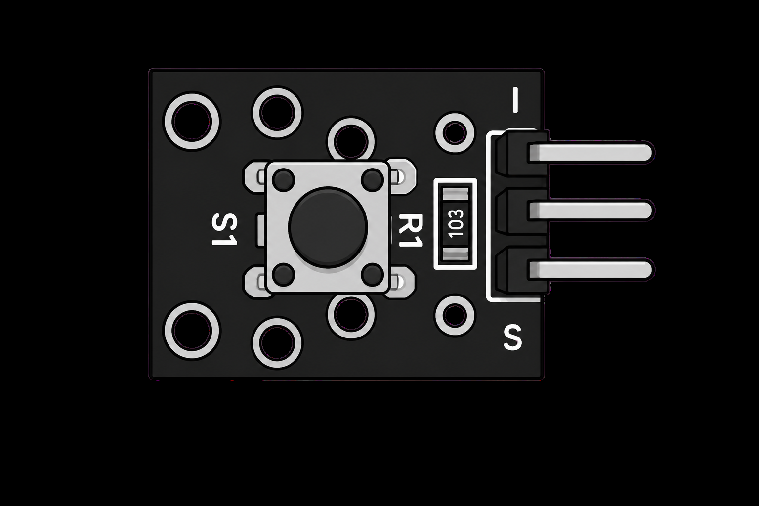
Look at the board and you'll find two parts. S1 is a tactile switch: press it and a metal dome snaps down and joins its contacts. R1 is a small resistor marked 103, which means 10 followed by three zeros: 10,000 ohms. The header has three pins: S for the signal, a middle pin for power (+) and − for ground.
R1 connects S to the + pin, so with nothing pressed, S sits at 5 V and reads HIGH. Press the button and S1 connects S straight to ground. A direct path to ground easily beats a 10k resistor, so S drops to 0 V and reads LOW. The course's own notes on this lesson say the same thing: the pin is HIGH until the button is pressed, then it goes LOW.
Why bother with the resistor at all? An input pin with nothing connected floats: it picks up stray charge from your hand and nearby wires and reads HIGH and LOW at random. The resistor gives the pin a definite resting level, and the button overrides it. This arrangement is called a pull-up, and you'll meet it again on the joystick's push switch and the rotary encoder's knob.
Wiring it to the HERO Board
| KY-004 pin | HERO Board pin | What it does |
|---|---|---|
| S | D4 | The signal: HIGH at rest, LOW while pressed |
| + (middle pin) | 5V | Feeds the pull-up resistor |
| − | GND | The button joins S to this when pressed |
Pins from the SensorKit lesson's code. The filmed walkthrough wires S to D2, from an earlier version of the sketch; either works as long as the code reads the pin you wired.
Why D4? The lesson's comments explain the choice, and it's a habit worth copying. D0 and D1 carry the USB serial link. D2 and D3 are the only pins that can trigger interrupts. D3, D5, D6, D9, D10 and D11 are the PWM pins. D11 to D13 form the SPI bus, and D13 also drives the built-in LED. A button needs none of that, so the course puts it on D4, D7 or D8 and keeps the special pins free for parts that need them.
The walkthrough's code
const int KY_004_PIN = 4;  // the module's S pin

void setup() {
  pinMode(LED_BUILTIN, OUTPUT);       // the board's own LED (D13)
  pinMode(KY_004_PIN, INPUT_PULLUP);  // the button is an input
}

void loop() {
  if (digitalRead(KY_004_PIN) == LOW)  // pressed: S is LOW
    digitalWrite(LED_BUILTIN, HIGH);   // LED on
  else
    digitalWrite(LED_BUILTIN, LOW);    // LED off
}INPUT_PULLUPturns on a pull-up resistor inside the chip, on top of R1. You don't strictly need both, but it means the sketch still works if the + pin is left unconnected, which is the most common slip with this module.LED_BUILTINis pin 13 on Uno-compatible boards: the small LED soldered beside the pin header. You see the result without wiring anything else.- The
ifchecks for LOW because LOW is the pressed state. Read it as "if the button is down". - There's no
delay(). The loop runs many thousands of times a second, so the LED follows your finger with no lag you could see.
One press, one event
Copying the button onto the LED hides a problem you'll hit the moment you count presses or toggle something. The contacts inside S1 are springy metal, and they bounce for a few milliseconds when they meet. Your board is fast enough to see every bounce, so one press can read as three. The debouncing article in the Help Center shows what that looks like.
The fix is to wait until the reading holds still before you believe it. This sketch toggles the board's LED once per press:
const int BUTTON_PIN = 4;   // KY-004 S: joined to GND when pressed
const int LED_PIN = 13;     // the LED built into the board
const unsigned long SETTLE_MS = 30;   // a press bounces for a few ms: wait for it to settle

bool ledOn = false;
int lastReading = HIGH;
int pressed = HIGH;          // the button's settled state
unsigned long changedAt = 0;

void setup() {
  pinMode(BUTTON_PIN, INPUT_PULLUP);   // reads HIGH until the button is pressed
  pinMode(LED_PIN, OUTPUT);
  Serial.begin(9600);
}

void loop() {
  int reading = digitalRead(BUTTON_PIN);
  if (reading != lastReading) changedAt = millis();
  lastReading = reading;
  if (millis() - changedAt > SETTLE_MS && reading != pressed) {
    pressed = reading;
    if (pressed == LOW) {   // a new press
      ledOn = !ledOn;
      digitalWrite(LED_PIN, ledOn ? HIGH : LOW);
      Serial.println(ledOn ? "LED on" : "LED off");
    }
  }
}Every change in the reading restarts a clock. Only when the reading has held the same value for 30 ms (SETTLE_MS) does the sketch accept it as the button's new state. Then pressed == LOW catches the moment of the press, not the whole time you hold it, so each press flips the LED exactly once, however long your finger stays down.
What to build with it
- A start button. Plenty of builds wait for a press before they begin, like a countdown timer that starts when you press its knob in.
- A toggle, like the sketch above: one press for on, the next for off. That's how a power or mute button works.
- A doorbell or a game buzzer, paired with the KY-012 active buzzer: its page has a sketch that beeps twice each time the KY-004 is pressed.
You can try all of this before you wire anything: the KY-004 is one of the parts in the free browser simulator. Hold it down with the mouse and the pin reads LOW, like the real board.
When it doesn't work
- The LED is always on. The pin reads LOW all the time: S is touching the ground row on the breadboard, or the code reads a different pin from the one you wired.
- The LED flickers, or turns on when your hand comes near. The pin is floating. Use
INPUT_PULLUP, or connect + to 5V so R1 can do its job. - One press counts as two or three. That's contact bounce. Use the settle time from the toggle sketch.
- Nothing happens at all. Check the pin number first: the walkthrough video uses D2, the lesson's code uses D4. Then check the + and − wires.
Watch the module wired on the bench in the KY-004 walkthrough, part of the free SensorKit course, and see where it sits among the other modules in the 37-in-1 sensor kit guide.
37-in-1 Sensor Kit: The KY-004 and 36 more modules in a latching case, with the free SensorKit course: 31 filmed walkthroughs and their code.
HERO Board: The Uno-compatible board every SensorKit walkthrough is filmed on, with its USB cable.
Questions
Why does the KY-004 read LOW when the button is pressed?
Its 10k resistor pulls the signal pin up to 5 V while the button is open, and pressing the button connects the pin straight to ground. So it rests HIGH and reads LOW while pressed. This is called a pull-up, and most buttons are wired this way.
Do I need to add a resistor to the KY-004?
No. The 10k pull-up (the resistor marked 103) is on the board. Using INPUT_PULLUP in your code adds the chip's own pull-up as well, so the button works even if the + pin isn't connected.
Which pin should I connect the KY-004 to?
Any digital pin works, and A0 to A5 can read it too. The SensorKit lesson uses D4 so the interrupt, PWM and SPI pins stay free for modules that need them. Whatever you choose, the pin in your code has to match.
Why does one press count more than once?
The metal contacts bounce for a few milliseconds when they close, and the board sees each bounce. Wait for the reading to hold steady for about 30 ms before you accept it, as the toggle sketch on this page does.