Steer a servo with a joystick
Updated
This is the build where code starts moving things. Push a joystick left and a servo's arm swings to one end; push it right and it swings to the other; let go and it settles in the middle. The same loop steers pan-and-tilt camera mounts, robot arms and remote-control rudders.
It takes two parts, eight wires and a sketch of about twenty lines, the one that passed its test in our simulator. Then you'll add a second axis, make the stick steer instead of point, and fix the two problems servo builds run into most.
What you'll build and learn
- Reading a joystick. Each axis is a knob inside the stick, so
analogRead()gives 0 at one end, about 512 in the middle and 1023 at the other: analog input. - map(), which rescales 0 to 1023 into 0 to 180 degrees in one line: map().
- The Servo library, which turns an angle into the pulses a servo understands.
- Change detection: printing only when the angle actually changes, so the Serial Monitor stays readable.
Run it: The joystick and servo, running · The finished build in the CraftingTable simulator: the same parts, wiring and code as this page.
Parts
| Part | How many | Notes |
|---|---|---|
| HERO Board or HERO XL | 1 | The example was tested on the HERO Board; the HERO XL runs it unchanged |
| Joystick module | 1 | 5 pins: GND, +5V, VRx, VRy, SW |
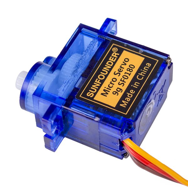
| Small servo | 1 | 3 wires: ground, power, signal |
| Breadboard | 1 | For the shared 5V and GND rails |
| Jumper wires | 8 |
Pandora's Box has both parts, the joystick module and the servo, and each has its own part tutorial in the course: 180 Degree Servo and Joystick Module. Its board is the HERO XL, which has the same A0 and pin 9 this sketch uses, so the code runs as it is. The 37-in-1 Sensor Kit has a joystick too, the KY-023, but no servo.
Wiring
| Part pin | Goes to | Notes |
|---|---|---|
| HERO Board 5V | Breadboard 5V rail | |
| HERO Board GND | Breadboard GND rail | |
| Joystick +5V | 5V rail | Power for the stick |
| Joystick GND | GND rail | |
| Joystick VRx | A0 | Left and right |
| Servo power (red) | 5V rail | |
| Servo ground (brown or black) | GND rail | |
| Servo signal (orange or yellow) | D9 | The pulses that set the angle |
VRy and SW stay unconnected for now. Servo wire colors vary by maker; check yours.
The joystick and the servo share the 5V and GND rails with the board. The ground matters most: the servo reads its signal against ground, so if its ground wire isn't joined to the board's, it ignores every pulse.
The code
No libraries to install: Servo comes with the Arduino IDE. Upload this and open the Serial Monitor at 9600 baud.
// Joystick servo: push the stick left or right and the servo turns to match.
#include <Servo.h>

Servo servo;
const int STICK_X = A0;   // the joystick's left-right axis: 0 left, about 512 centred, 1023 right
int lastAngle = -1;

void setup() {
  servo.attach(9);
  Serial.begin(9600);
}

void loop() {
  int angle = map(analogRead(STICK_X), 0, 1023, 0, 180);
  servo.write(angle);
  if (angle != lastAngle) {
    Serial.print("Angle ");
    Serial.println(angle);
    lastAngle = angle;
  }
  delay(20);
}How the code works
From stick to angle
analogRead(STICK_X) measures the left-right knob inside the joystick: 0 pushed fully one way, about 512 centered, 1023 fully the other way. map(reading, 0, 1023, 0, 180) rescales that onto the servo's range, so the middle of the stick lands near 90 degrees, the middle of the servo. map() uses whole numbers, so the angle steps one degree at a time.
From angle to movement
servo.attach(9) hands pin 9 to the Servo library. From then on the library sends a pulse about 50 times a second, and the length of each pulse, between roughly half a millisecond and two and a half, tells the servo where to stand. servo.write(angle) changes that length. The servo's own little circuit does the rest: it drives the motor until the arm matches, and holds it there.
Printing only changes
lastAngle remembers what was printed last, and the sketch prints only when the angle changes. Without that check, the Serial Monitor would scroll the same number fifty times a second. delay(20) paces the loop to the servo's own rhythm of about 50 updates a second.
Try it without parts
The joystick and the servo are both parts in the free browser simulator. Wire them to a HERO Board, paste the sketch, press Run and drag the stick on screen: the servo's arm follows, and the angle prints below.
Make it yours
- Two axes, two servos. Wire VRy to A1 and a second servo's signal to D10, then copy the lines for a second
Servoobject. Left-right and up-down on one stick is a pan-and-tilt mount. - Steer instead of point. Instead of mapping the stick straight to an angle, nudge the angle a little each loop in the direction the stick leans, and keep it in range with constrain(). Let go and the arm stays where it is.
- Center on a click. Pressing the stick closes its SW pin. Wire SW to a free pin with
INPUT_PULLUP, and when it reads LOW, send the servo to 90.
Common problems
- The servo jitters or hums with the stick at rest. The reading wobbles by a count or two around the center, and now and then that crosses into the next degree. Ignore changes of one degree, or treat a small band around 512 as dead center.
- The board resets or the USB connection drops when the servo moves. A servo draws a burst of current as it starts, more under load, and the USB port can sag. Power the servo from a separate 5 V supply and join its ground to the board's GND.
- The servo doesn't move at all. Check the signal wire is on D9 and that the servo's ground reaches the board's GND. Watch the Serial Monitor: if the angles change as you move the stick, the problem is on the servo side.
- It turns the wrong way. Swap the last two numbers in
map(), to180, 0, or turn the joystick round. - An LED on pin 10 stopped dimming. On the HERO Board the Servo library takes over the timer behind PWM on pins 9 and 10, so
analogWrite()there stops working. Move the LED to pin 3, 5, 6 or 11.
Adventure Kit: Pandora's Box: The HERO XL with a joystick, a servo, a stepper motor and more than 30 kinds of parts, and a story that builds a sweep radar and a joystick-aimed light turret.
Questions
How do I control a servo with a joystick?
Read one of the joystick's axes with analogRead(), which gives 0 to 1023, rescale it to 0 to 180 with map(), and pass the result to servo.write(). The sketch on this page does exactly that, about 50 times a second.
Can I power a servo from the board's 5V pin?
A small servo with nothing on its arm usually runs fine from it. Under load, or if the board resets when the servo moves, give the servo its own 5 V supply and connect the two grounds.
Which pins can a servo use?
The Servo library can drive a servo from any digital pin. On the HERO Board, using the library turns off analogWrite() dimming on pins 9 and 10, whichever pins your servos are on.
Why does my servo twitch when the joystick is centered?
The center reading isn't perfectly steady, so the angle flickers between two neighboring degrees. Ignore one-degree changes, or treat readings close to 512 as exactly centered.