KY-018 photoresistor module: wiring, code and a night light
Updated
The KY-018 is the simplest sensor in the 37-in-1 kit: a photoresistor and one resistor. Wire it up, cover it with your hand, and the number on your screen jumps up.
Up, not down. That surprises almost everyone, especially if you've wired a photoresistor before in 30 Days Lost in Space, where covering it makes the number fall. It isn't a fault. It's how the module is built, and once you see why, you can set thresholds that hold and build a night light that doesn't argue with itself.
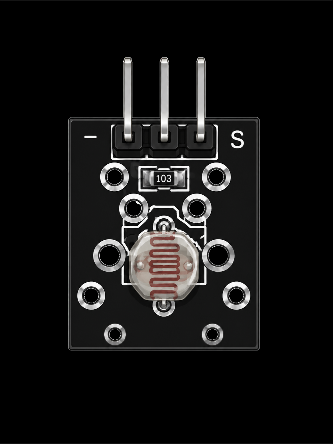
What's on the board
- A photoresistor, also called an LDR (light-dependent resistor): the disc with the squiggly track. Its resistance is low in bright light and very high in the dark.
- A 10 kΩ resistor (marked 103).
- A 3-pin header: minus for ground, the middle pin for 5 V, and S for the signal.
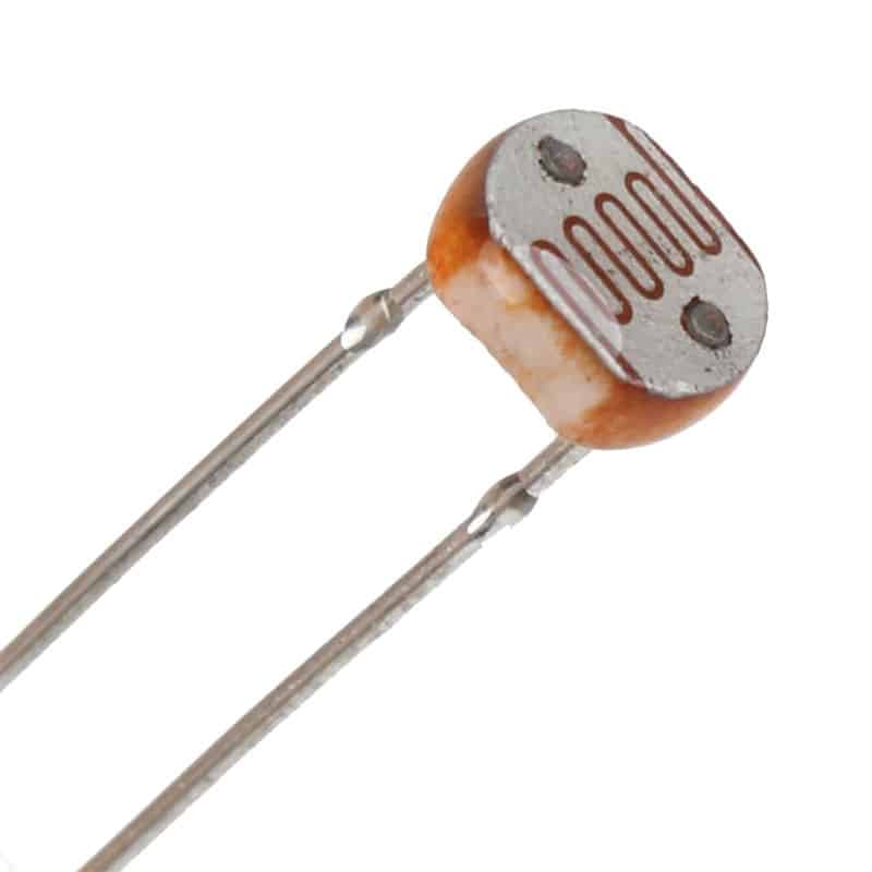
Those two parts make a voltage divider: two resistances in series between 5 V and ground, with S tapped off the point between them. Your board can't measure resistance, but analogRead() can measure the voltage at that point, and that voltage depends on the ratio of the two resistances.
Why the reading goes up in the dark
Cover the module in the walkthrough and the plotted value spikes upward. That tells you which way round the divider is built: the fixed 10 kΩ resistor joins S to 5 V, and the photoresistor joins S to ground.
Now follow the light. In the dark the photoresistor's resistance climbs very high, so it takes almost all of the 5 V and S sits close to 5 V. In bright light its resistance falls and S is pulled toward ground. The reading works out as 1023 × R / (R + 10 kΩ), where R is the photoresistor's resistance:
| Light | Photoresistor (typical) | Voltage at S | analogRead() |
|---|---|---|---|
| Bright | About 1 kΩ | About 0.45 V | About 93 |
| Room light | About 10 kΩ | About 2.5 V | About 512 |
| Dark | About 1 MΩ | About 4.95 V | About 1013 |
Typical photoresistor values from the Help Center's photoresistor article. Every cell and every room differs, so trust the shape, not the exact numbers.
The 30 Days kit wires its photoresistor the other way round, on the 5 V side, so there more light means a higher number. Neither is wrong; it's the same voltage divider turned over. If you'd rather the KY-018 count up with the light, flip it in code instead of rewiring: int light = 1023 - analogRead(A0);
Wiring the KY-018 to the HERO Board
| KY-018 pin | HERO Board | What it carries |
|---|---|---|
| Minus (-) | GND | Ground |
| Middle (+) | 5V | Power for the divider |
| S | A0 | The light reading (any of A0 to A5 works) |
The course's code reads A0. In the walkthrough the S wire goes to A5, which works the same once the pin in the code matches. The instructor also stops to check which outer pin is ground before plugging in, and so should you: minus to GND, middle to 5V.
The walkthrough's code
This is the KY-018 sketch from the SensorKit course. It prints the reading and blinks the board's built-in LED, using the reading itself as the delay:
uint8_t sensorPin = A0;   // the module's S pin
int ledPin = 13;          // the board's built-in LED

void setup() {
  pinMode(ledPin, OUTPUT);
  Serial.begin(115200);
}

void loop() {
  int sensorValue = analogRead(sensorPin);
  Serial.println(sensorValue);
  digitalWrite(ledPin, HIGH);
  delay(sensorValue);
  digitalWrite(ledPin, LOW);
  delay(sensorValue);
}delay() takes milliseconds, so a reading of 500 means half a second on and half a second off. On this module darker means a higher reading, so covering the sensor slows the blink to a lazy flash, and a phone's flashlight makes it flicker fast. It's a neat way to see the backwards reading with no screen at all.
Open the Serial Monitor at 115200 baud to see the numbers, or Tools > Serial Plotter to watch them as a line, the way the walkthrough does. The analogRead article explains where the 0 to 1023 comes from.
Calibrate your thresholds
Never copy someone else's threshold. Your module, your room and your lamp all differ. Measure instead:
- Run the sketch above and note the reading in normal room light.
- Cover the sensor, or dim the room to the level you care about, and note that reading too.
- Put your threshold between the two. Remember that on this module the dark reading is the higher one.
Then use two thresholds instead of one. A single line flickers: at dusk the reading wanders back and forth across it, and whatever you're switching turns on and off with it. Switch on above one number and off below a lower one, and the gap between them (called hysteresis) soaks up the wobble.
If you'd rather think in percent, the map() function turns your two measured readings into 0 to 100: map(reading, brightReading, darkReading, 0, 100) gives you how dark it is.
Build it: a night light
You need the KY-018, an LED and a 220 Ω resistor (30 Days Lost in Space has both). Wire pin 9 to the resistor, the resistor to the LED's long leg, and the LED's short leg to GND. Or set LED_PIN to 13 and use the board's own LED. Then set the two numbers from your own calibration:
const uint8_t LIGHT_PIN = A0;   // the KY-018's S pin
const uint8_t LED_PIN = 9;      // the LED, through a 220 ohm resistor

// Set these from your own readings. On this module darker = HIGHER.
const int DARK_ON = 700;        // this dark or darker: light on
const int BRIGHT_OFF = 600;     // this bright or brighter: light off

bool lampOn = false;

void setup() {
  pinMode(LED_PIN, OUTPUT);
  Serial.begin(115200);
}

void loop() {
  int reading = analogRead(LIGHT_PIN);
  Serial.println(reading);

  if (!lampOn && reading > DARK_ON) lampOn = true;
  if (lampOn && reading < BRIGHT_OFF) lampOn = false;

  digitalWrite(LED_PIN, lampOn ? HIGH : LOW);
  delay(200);
}Between 600 and 700 nothing changes, and that's the point: the lamp keeps whatever state it was in, so a reading that hovers can't make it flicker.
One trap catches nearly everyone: point the LED away from the sensor. If the photoresistor can see its own lamp, the light switches on, the room looks bright, the light switches off, and round it goes. The gap between DARK_ON and BRIGHT_OFF helps, but distance helps more.
Want it to fade in instead of snapping on? Pin 9 is a PWM pin, so analogWrite() can set its brightness; the PWM article shows how.
Common problems
- The number goes up when it gets dark. That's the module's design, explained above. Flip it in code if you prefer.
- The reading drifts and ignores your hand. The S wire isn't on the pin your code reads. An analog pin with nothing on it floats and returns noise.
- It barely changes. Make sure the sensor's face isn't shaded by a wire, and compare real dark with real light. A sensor covered by fingers in a bright room still sees light leaking round them.
- It misses quick flashes. Photoresistors take tens of milliseconds to react: fine for daylight and lamps, too slow for counting fast pulses of light.
- The night light flickers. Use two thresholds, and point the LED away from the sensor.
Watch it, then go further
The KY-018 walkthrough is lesson 14 of the SensorKit course. For the rest of the case, see every module in the 37-in-1 sensor kit. The Help Center's photoresistor article goes deeper into the part itself: what it's made of, and how to calibrate with map().
37-in-1 Sensor Kit: The KY-018 and 36 more modules in a latching case, with the free SensorKit course: 31 filmed walkthroughs and example code.
30 Days Lost in Space: The HERO Board, a breadboard, LEDs, resistors and a photoresistor, with filmed lessons that teach you to wire and code from zero.
Questions
Why does my KY-018 read higher in the dark?
On the module the photoresistor sits between the signal pin and ground, with a 10 kΩ resistor up to 5 V. In the dark its resistance rises, so the signal voltage rises with it.
Which pins does the KY-018 use?
Its S pin is an analog output, so it goes to one of the HERO Board's analog inputs, A0 to A5. The course's code uses A0. Minus goes to GND and the middle pin to 5V.
Can the KY-018 measure light in lux?
Not accurately. A photoresistor isn't calibrated and no two are alike, so treat its reading as brighter or darker, and set thresholds by measuring in your own room.
Why does my night light flicker on and off?
Either the reading is wandering across a single threshold (use two, with a gap between them), or the sensor can see the LED it switches on (point the LED away).