KY-009 SMD RGB LED module: wiring, resistors and code
Updated
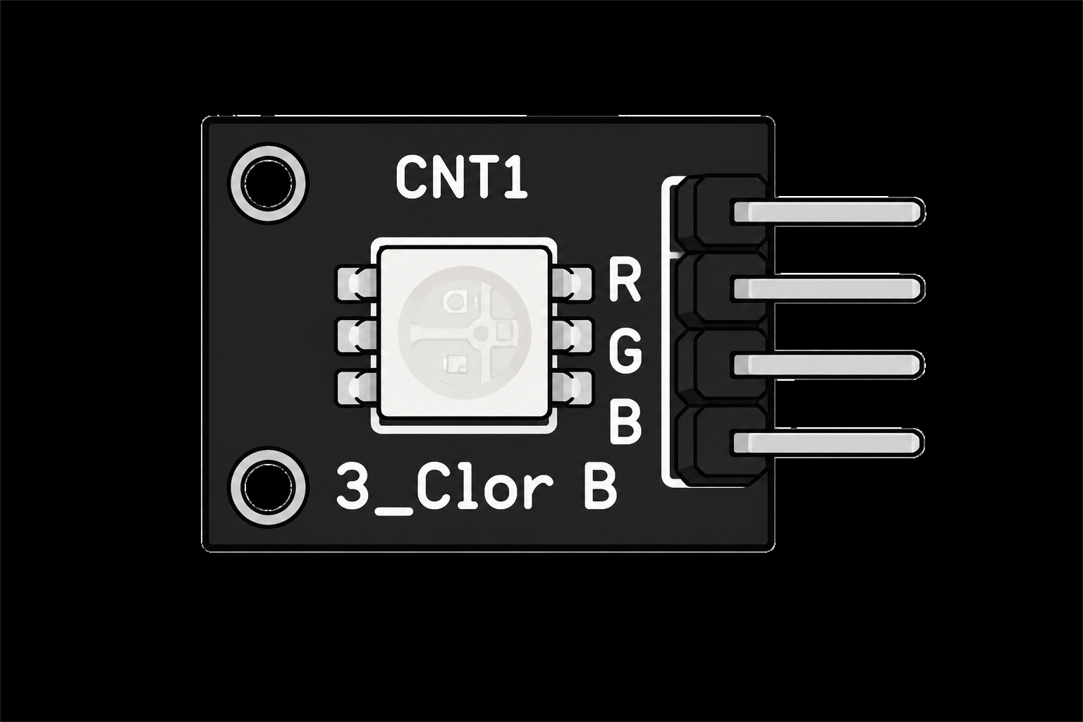
The KY-009 puts a flat, square RGB LED on a four-pin board: red, green and blue chips under one window, sharing a ground. Drive the three color pins at different strengths and your eye blends them into almost any color.
It looks like the KY-016 RGB LED with a flat lens, and it mixes color the same way. The difference that matters is underneath: the KY-009 has no resistors on the board. Here's how to wire it so it lasts, what the SensorKit course's code does line by line, and the label mix-up the course's own testers found.
Three LEDs under one flat window
The square part is a 5050 surface-mount LED, named for its 5.0 by 5.0 mm footprint. Under its window sit three tiny LED chips, one red, one green and one blue. They're so close together that at normal distance you see one point of light, and their colors add: red and green read as yellow, red and blue as magenta, all three as a slightly tinted white.
The three chips share their negative side, which is the module's fourth pin: a common cathode. So a color lights when its pin goes HIGH, and analogWrite() sets how bright. That's the whole board: the LED, a header printed R, G and B, and nothing in between.
Give each color its own resistor
The SensorKit lesson's code is blunt about this: you must put resistors between the module and the board to stop the LED burning out. Each color pin connects straight to an LED chip, and an LED wired directly to a 5 V pin draws more current than either the chip or the pin should carry.
Use one 220 ohm resistor per color. Don't save parts with a single resistor on the ground pin: red needs less voltage than green and blue, so with a shared resistor red takes most of the current and every mixed color leans orange. The RGB LED article in the Help Center goes into the numbers.
Wiring
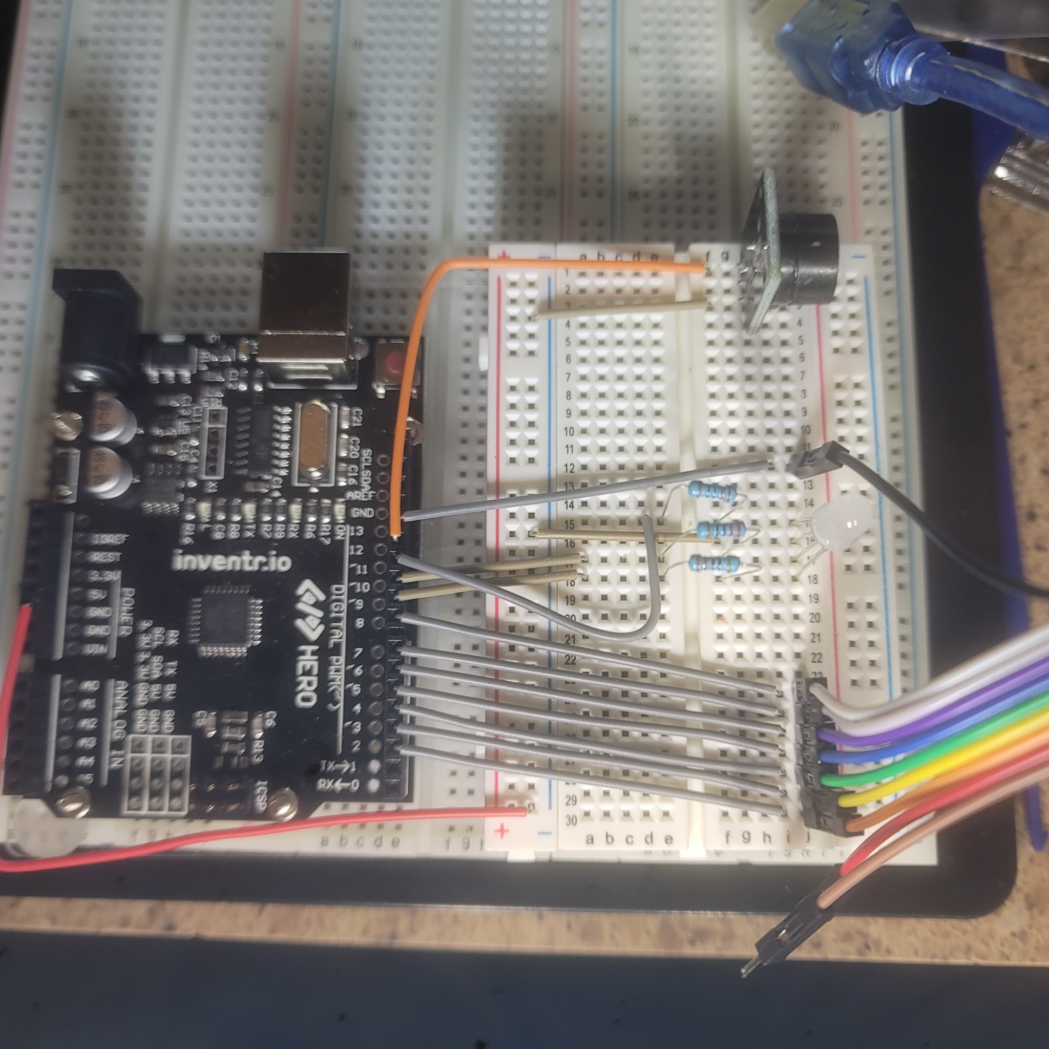
| KY-009 pin | HERO Board pin | Through |
|---|---|---|
| R | D6 | 220 ohm resistor |
| G | D5 | 220 ohm resistor |
| B | D9 | 220 ohm resistor |
| Fourth pin (ground) | GND | Direct |
Pins from the SensorKit lesson's code. The walkthrough video was filmed with an earlier sketch, so its wires land on different pins: follow the code you run.
Why 6, 5 and 9? Fading needs PWM, and only pins 3, 5, 6, 9, 10 and 11 have it (they're marked ~ on the board). The lesson skips 3 because it's one of the two interrupt pins, and 10 and 11 because they belong to the SPI bus. That leaves 5, 6 and 9.
Check the labels before you trust them
The course's code carries a warning worth knowing: on two modules the course team tested, the colors weren't on the pins the print says. Red and green were swapped. The sketch below makes this easy to catch, because it starts with a built-in test: red for one second, then green, then blue. If the first second isn't red, swap the red and green pin numbers in the code (or swap those two wires) and carry on.
The code, line by line
const int KY_009_RED_PIN = 6;
const int KY_009_GREEN_PIN = 5;
const int KY_009_BLUE_PIN = 9;

void setup() {
  pinMode(KY_009_RED_PIN, OUTPUT);
  pinMode(KY_009_GREEN_PIN, OUTPUT);
  pinMode(KY_009_BLUE_PIN, OUTPUT);
}

void loop() {
  analogWrite(KY_009_RED_PIN, 255);    // red for one second
  delay(1000);

  analogWrite(KY_009_RED_PIN, 0);
  analogWrite(KY_009_GREEN_PIN, 255);  // green for one second
  delay(1000);

  analogWrite(KY_009_GREEN_PIN, 0);
  analogWrite(KY_009_BLUE_PIN, 255);   // blue for one second
  delay(1000);
  analogWrite(KY_009_BLUE_PIN, 0);

  // fade slowly from color to color
  for (int i = 255; i > 0; i--) {
    analogWrite(KY_009_RED_PIN, i);
    analogWrite(KY_009_BLUE_PIN, 255 - i);
    analogWrite(KY_009_GREEN_PIN, constrain(128 - i, 0, 255));
    delay(10);
  }

  for (int i = 0; i < 255; i++) {
    analogWrite(KY_009_RED_PIN, i);
    analogWrite(KY_009_BLUE_PIN, 255 - i);
    analogWrite(KY_009_GREEN_PIN, constrain(128 - i, 0, 255));
    delay(10);
  }
  analogWrite(KY_009_GREEN_PIN, 0);
  analogWrite(KY_009_BLUE_PIN, 0);
}analogWrite(pin, 255)holds a color fully on and0turns it off. Values in between switch the pin on and off hundreds of times a second, and the share of time it's on is the brightness you see. The PWM article explains why your eye smooths it out.- The three one-second blocks are the label test: red, green, blue, in that order.
- In the first
forloop, red counts down from 255 while blue counts up, so the light slides from red to blue. Each of the 255 steps waits 10 ms: about two and a half seconds per sweep. The second loop slides it back. - Green follows
128 - i, which drops below zero for half of each sweep.analogWrite()only understands 0 to 255, so the sketch wraps it in constrain(), which clamps any value into a range: green glows during the middle of the sweep and rests at zero the rest of the time.
KY-009 or KY-016?
As the walkthrough's instructor puts it, they're the same thing in a different package: a flat LED against one that sticks out. They take the same code. Reach for the KY-016 when you want to wire straight to pins, because it carries three resistors on its board. Reach for the KY-009 when you want a flat light that sits flush behind a panel or a diffuser, and you don't mind adding three resistors.
What to build with it
- A status light. Day 14 of 30 Days Lost in Space uses an RGB LED as a security panel's status: green for clear, red for alarm. The flat KY-009 does that job behind a front panel.
- A mood lamp that fades between named colors, like the mood lamp example verified in the CraftingTable simulator.
- A color gauge for another sensor in the kit: put a temperature or light reading on the red-to-blue fade above.
When it doesn't work
- One color never lights. Its wire is on the wrong pin, its resistor isn't in the same breadboard row, or that chip burned out on an earlier run without resistors.
- Red shows as green. It's the label swap above: swap the two pin numbers in the code.
- Mixed colors look orange. You used one resistor on the ground pin instead of one per color.
- A color is only ever fully on or off. Its pin has no PWM. Use 5, 6 and 9, or any three of the ~ pins.
The KY-009 is a part in the free browser simulator, so you can try your fades before you wire. Watch the real module in the KY-009 walkthrough, and find the rest of the kit in the 37-in-1 sensor kit guide.
37-in-1 Sensor Kit: The KY-009 and KY-016 RGB modules and 35 more in a latching case, with the free SensorKit course.
30 Days Lost in Space: The HERO Board, a breadboard, resistors and an RGB LED, with the filmed lessons that build the Day 14 security panel.
Questions
Does the KY-009 need resistors?
Yes. The board has none, and the SensorKit lesson says to add them to stop the LED burning out. Put one 220 ohm resistor in each color line, not one shared resistor on ground.
Is the KY-009 common anode or common cathode?
Common cathode. The three colors share the ground pin, so a color turns on when its pin goes HIGH and analogWrite() values closer to 255 make it brighter.
What's the difference between the KY-009 and the KY-016?
The KY-009 is a flat 5050 surface-mount LED with no resistors on the board. The KY-016 is a 5 mm through-hole LED with three resistors on the board, so it wires straight to pins. They use the same code.
Why are red and green swapped on my KY-009?
Some batches are printed with the wrong labels: the SensorKit course found red and green swapped on two of the modules it tested. Swap the two pin numbers in your code and it's fixed.