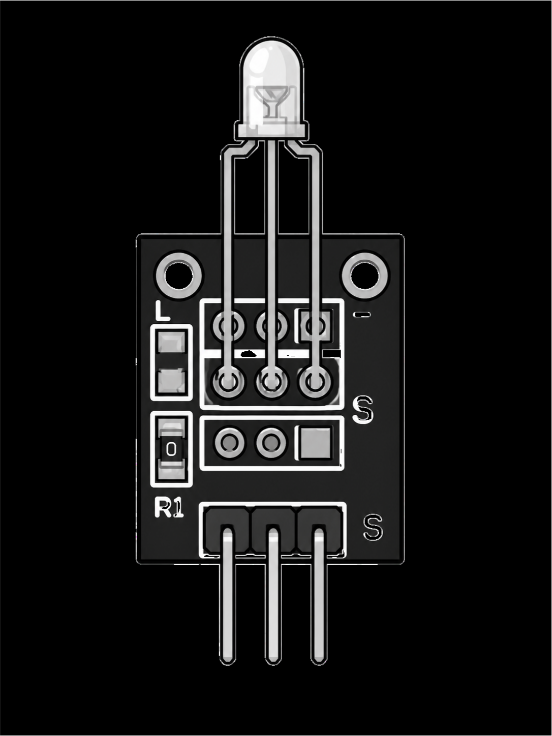
KY-011 and KY-029 two color LED modules: wiring and code
Updated
The KY-011 and the KY-029 are one idea in two sizes: a single LED bulb holding a red chip and a green chip, with three pins to drive them. The KY-011 has a 5 mm bulb and the KY-029 a 3 mm one. They wire the same, take the same code, and the SensorKit course uses the identical sketch for both.
So they share this page. Here's which pin is which, how the course wires them to the HERO Board, what the fade code does step by step, and how to turn two colors into a gauge that runs from green through amber to red.
Two LEDs in one bulb
Inside the bulb sit two LED chips that share their negative side, a common cathode, which comes out on the − pin. Each chip has its own positive pin. Light only the red and you get red, only the green and you get green, and both at once blend into amber or orange. The walkthroughs show exactly that: the light fades from red to green and passes through orange on the way.
The instructor describes the second color as "kind of yellow", and that's worth knowing before you buy into the name: expect a yellow-green rather than a deep traffic-light green. Two colors plus the blend between them give you three clear states from one small part, which is what makes these modules such good status lights.
Which pin is which
| Module pin | Drives | HERO Board pin |
|---|---|---|
| − | Ground, shared by both chips | GND |
| Middle pin | The red LED | D11 |
| S | The green LED | D10 |
Pin roles as on the KY-011 and KY-029 boards; HERO Board pins from the SensorKit lessons' code, which sets red to 11 and green to 10.
If your colors come out the other way round, swap the two signal wires, or swap the numbers in the code. Nothing else changes: the two chips are identical apart from their color. Both D10 and D11 are PWM pins (marked ~), which is what lets the course fade them instead of only switching them.
The course wires both color pins straight to the board. For a build that will stay lit for hours, a 220 ohm resistor in each color line is cheap insurance for the LED and the pins, at the cost of a little brightness.
The course's code, line by line
int redpin = 11;    // red LED
int greenpin = 10;  // green LED
int val;

void setup() {
  pinMode(redpin, OUTPUT);
  pinMode(greenpin, OUTPUT);
}

void loop() {
  for (val = 255; val > 0; val--) {
    analogWrite(greenpin, val);
    analogWrite(redpin, 255 - val);
    delay(15);
  }
  for (val = 0; val < 255; val++) {
    analogWrite(greenpin, val);
    analogWrite(redpin, 255 - val);
    delay(15);
  }
}analogWrite()takes 0 (off) to 255 (fully on). It works by switching the pin on and off hundreds of times a second; the PWM article explains why you see a steady glow.- Green gets
valand red gets255 - val, so the two always add up to 255. Asvalfalls, green dims exactly as fast as red brightens, and the light travels from green, through amber, to red. - Each step waits 15 ms. 255 steps make one sweep about 3.8 seconds long, the second loop brings it back, and a full cycle takes a little over 7.5 seconds.
- Want to see one color alone? Replace the loops with
analogWrite(redpin, 255); analogWrite(greenpin, 0);and it holds pure red, as the walkthrough suggests trying.
Turn it into a gauge
A status light is the most useful thing these modules do. This sketch shows a level from 0 to 100: green when it's low, amber in the middle, red at the top. Feed it a temperature, a light level, or a count of something.
const int RED_PIN = 11;
const int GREEN_PIN = 10;

// 0 shows green, 100 shows red, and the values between blend through amber.
void showLevel(int percent) {
  percent = constrain(percent, 0, 100);
  analogWrite(RED_PIN, map(percent, 0, 100, 0, 255));
  analogWrite(GREEN_PIN, map(percent, 0, 100, 255, 0));
}

void setup() {
  pinMode(RED_PIN, OUTPUT);
  pinMode(GREEN_PIN, OUTPUT);
}

void loop() {
  for (int p = 0; p <= 100; p += 10) {   // a test sweep: replace with a real reading
    showLevel(p);
    delay(500);
  }
}map() rescales 0 to 100 onto 0 to 255, and constrain() stops a stray value from going out of range. Both have Help Center articles: map() and constrain(). To show a sensor instead of the test sweep, call showLevel(map(analogRead(A0), 0, 1023, 0, 100)) with the sensor's signal on A0.
KY-011 or KY-029?
In code there's no difference at all. Choose by size: the KY-011's 5 mm bulb is easier to spot from across a room, and the KY-029's 3 mm bulb fits where space is tight or the light shows through a small hole in a panel. As the KY-029 walkthrough puts it, it works exactly the same as the other LEDs, it's just smaller.
When it doesn't work
- Only one color ever lights. The other signal wire is loose or a row off on the breadboard, or the code drives a pin you didn't wire.
- The colors are the wrong way round. Swap the two signal wires, or swap the numbers in
redpinandgreenpin. - It snaps between colors instead of fading. One of the pins has no PWM. Use two of 3, 5, 6, 9, 10 and 11.
- Nothing at all. Check that − is on GND and not on a signal pin.
The KY-029 is a part in the free browser simulator; the KY-011 isn't yet, but with the same pins and code, the KY-029 stands in for it. Watch both on the bench in the KY-011 walkthrough and the KY-029 walkthrough. For full color, the KY-016 RGB LED adds a blue chip, and the 37-in-1 sensor kit guide covers every other module in the case.
37-in-1 Sensor Kit: Both two color LED modules and 35 more in a latching case, with the free SensorKit course and its code.
HERO Board: The Uno-compatible board every SensorKit walkthrough is filmed on, with its USB cable.
Questions
What's the difference between the KY-011 and the KY-029?
Only the size of the bulb: the KY-011 is 5 mm and the KY-029 is 3 mm. Both hold a red and a green LED with a shared ground, use the same pins, and run the same SensorKit code.
Can a two color LED make yellow or orange?
Yes, by mixing. Light the red and the green together and they blend into amber or orange; change the balance with analogWrite() to move between them.
Which pins does the SensorKit course use?
Red on D11 and green on D10, both PWM pins, with the − pin on GND.
Do the KY-011 and KY-029 need resistors?
The SensorKit course wires them straight to the pins. For builds that stay lit for a long time, adding a 220 ohm resistor in each color line protects the LED and the pins.