KY-002 shock sensor module: how it works, wiring and code
Updated
The KY-002 is the simplest motion detector in the 37-in-1 kit: a little spring sealed inside a round housing. Knock the board, flick it, or bump the table it sits on, and the spring swings over and touches a contact.
That touch lasts a fraction of a second, and it's all your code gets. Catching it every time is the whole trick with this module, and it explains why the course's sketch is written the way it is.
What's on the board
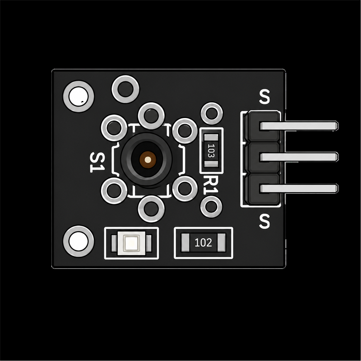
The round part in the middle is the vibration switch. At rest the spring inside hangs free and the switch is open. A knock makes it wobble against a contact, closing the circuit for an instant before it springs back. Beside it is a resistor that holds the signal pin at a steady level while the switch is open, so the pin never floats. The three header pins are S (signal), + in the middle for 5 V, and − for ground.
There's no chip, no knob and no analog output. The KY-002 reads as a plain digital input: one level at rest, the other for the moment the spring touches. It can tell you that a knock happened. It can't tell you how hard.
Wiring it to the HERO Board
| Module pin | HERO Board pin | What it carries |
|---|---|---|
| S | 10 | The signal |
| + (middle) | 5V | Power |
| − | GND | Ground |
Pin 10 matches the course sketch. Any digital pin works if you change the number in the code.
The course code carries a note on choosing pins that's worth knowing for every project. Pins 0 and 1 carry the USB link to your computer, so leave them free. Pin 13 drives the board's L LED. Pins 2 and 3 are the ones that can trigger interrupts, and the pins marked ~ can do PWM. If a project might need those jobs later, park simple switches on 4, 7 or 8. On its own, pin 10 is fine.
The code from the course
This is the sketch from the KY-002 walkthrough, with its comment banner trimmed. It copies the signal pin straight onto the board's L LED.
const uint8_t KY_002_PIN = 10;  // the module's S pin

void setup() {
  pinMode(LED_BUILTIN, OUTPUT);  // the board's L LED
  pinMode(KY_002_PIN, INPUT);
}

void loop() {
  int val = digitalRead(KY_002_PIN);
  if (val)
    digitalWrite(LED_BUILTIN, HIGH);
  else
    digitalWrite(LED_BUILTIN, LOW);
}Notice what isn't there: no delay(). The loop runs many thousands of times a second, so even a brief touch of the spring shows up on the LED as a flicker. Add a delay(500) and you'll start missing knocks, because the board spends most of every half second not looking. That's the rule for every quick-pulse sensor: read it often, and do slow jobs with millis() timing instead of delay().
Make it remember a knock
Mirroring the pin is good for testing, but a flicker is easy to miss. An alarm should latch: notice one knock and stay tripped. This version reads the pin once while the module sits still, remembers that as normal, then lights the LED for good the first time the reading changes. Press the board's reset button to arm it again.
const uint8_t KY_002_PIN = 10;
int restState;

void setup() {
  pinMode(LED_BUILTIN, OUTPUT);
  pinMode(KY_002_PIN, INPUT);
  restState = digitalRead(KY_002_PIN);  // what it reads while still
}

void loop() {
  if (digitalRead(KY_002_PIN) != restState) {
    digitalWrite(LED_BUILTIN, HIGH);    // tripped, and it stays on
  }
}Because it learns the resting level when the board starts, it works whichever way your module's signal swings. Just keep the module still for that first moment after power-up.
Shock sensor or tap sensor?
The kit has two spring sensors, and they're easy to mix up. The KY-002's spring is enclosed in the round housing on the face of the board. The KY-031 tap sensor has its spring in a clear plastic case on the edge, where you can watch it move. Both close a contact when shaken and both read as digital. The course uses them differently: the KY-002 sketch reacts to any movement, the KY-031 sketch counts taps one at a time.
So if you need to know that something moved at all, start with the KY-002. If you want a person to tap out a pattern, use the KY-031. And if the question is which way up something is, rather than whether it was disturbed, you want a tilt switch: the KY-017 or the KY-020.
What to build with it
- A drawer or box alarm. Fix the module inside the lid and run the latching sketch. If anyone opens it while you're out, the LED is waiting for you.
- A knock-to-wake gadget. Leave a light, a tune or a display asleep until someone knocks on the desk it sits on.
- A bump counter. Count how often a door slams or a toy gets dropped. Count changes in the reading, not the readings themselves, or one knock adds thousands; the KY-031 page shows how.
Common problems
- Nothing happens. Check S goes to the pin your code names (10 in the course sketch) and that + and − aren't swapped. Then add
Serial.begin(9600);tosetup()andSerial.println(digitalRead(10));to the loop, open the Serial Monitor and flick the module. You should see the value change. - The LED is on all the time and blinks off when you knock. Nothing is wrong. The sketch shows the pin's level, and if your module rests HIGH, the LED rests on. Swap
HIGHandLOWin theifto turn it the other way round. - It trips by itself. It's doing its job. Footsteps, a washing machine or a closing door all shake a table. Mount it on something stiff, away from the source, or only react when several knocks arrive within a second.
- It misses knocks. The loop is too slow. Take out long
delay()calls so the board is looking when the spring touches.
Watch it on the bench
The KY-002 walkthrough in the free SensorKit course wires this exact circuit on a HERO Board and flicks the module on camera, in under two minutes. Every other module in the case is covered in the 37-in-1 sensor kit guide, and the digital I/O article explains pinMode() and digitalRead() from scratch.
37-in-1 Sensor Kit: The KY-002 and 36 more modules in a latching case, with the free SensorKit course: 31 filmed walkthroughs and example code.
HERO Board: The Uno-compatible board every SensorKit walkthrough is filmed on, with its USB cable.
Questions
What does the KY-002 shock sensor detect?
Vibration and sudden movement. A spring inside touches a contact when the module is knocked, flicked or shaken, and the signal pin changes for that instant. It tells you a knock happened, not how hard it was.
Is the KY-002 analog or digital?
Digital. It's a spring switch and a resistor, so you read it with digitalRead(). There's no analog output and no sensitivity knob.
What's the difference between the KY-002 and the KY-031?
Both are spring switches. The KY-002's spring is enclosed in a round housing, and the course uses it to react to any movement. The KY-031 tap sensor has its spring in a clear case, and the course uses it to count taps.
Why does my KY-002 miss some knocks?
The contact lasts only a moment. If your loop has a long delay(), the board isn't looking when it happens. Keep the loop fast, or latch the first change as the alarm sketch on this page does.