What resistor do I need for an LED?
Updated
Short answer: 220 Ω. On a 5 V board like the HERO Board it suits every common LED color. On a 3.3 V board like the Raspberry Pi Pico it still works well for red and yellow.
The longer answer is one line of arithmetic, and it's worth knowing. It's what tells you what to do with a blue LED on a 3.3 V board, why your LED is dimmer than the sum predicted, and what happens if the only resistor in the drawer is a 1 kΩ.
Why an LED needs a resistor at all
An LED doesn't behave like a bulb. Below a certain voltage, its forward voltage, almost no current flows. Just above it, the current shoots up, and nothing inside the LED holds it back. Wire one straight to a 5 V pin and it draws far more than the 20 mA or so it's built for, then fails, sometimes instantly.
The resistor takes up the extra voltage so the current settles where you choose. It doesn't matter which side of the LED it sits on: in a single loop, the same current flows through every part.
The free browser simulator models this. Wire an LED to a pin with no resistor and it marks the LED burnt out, as it does for any LED drawing more than about 25 mA. It's the cheapest way there is to make the mistake once.
The formula
Everything below comes from Ohm's law, rearranged: resistance = (supply voltage minus LED voltage) ÷ current. Three numbers go in:
- Supply voltage: what the pin puts out when it's HIGH. 5 V on the HERO Board and other Uno-compatible boards, 3.3 V on the Raspberry Pi Pico.
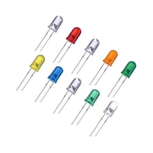
- LED voltage, the forward voltage: what the LED keeps for itself. It depends on the color, from about 2 V for red to about 3.2 V for blue and white.
- Current: how much you want flowing. LEDs are typically rated around 20 mA. 10 to 15 mA is plenty bright, and less is fine.
Worked once, for a red LED on a 5 V pin at the full 20 mA: (5 V minus 2 V) ÷ 0.020 A = 150 Ω. That's the smallest safe value. The common value just above it is 220 Ω, which gives 3 V ÷ 220 Ω = 13.6 mA: bright, and well inside the limits of both the LED and the pin, which is rated for 20 mA continuous.
On a 5 V board, by LED color
| LED color | Forward voltage | Smallest resistor (20 mA) | With 220 Ω | With 1 kΩ |
|---|---|---|---|---|
| Red | 2.0 V | 150 Ω | 13.6 mA | 3.0 mA |
| Yellow | 2.1 V | 145 Ω | 13.2 mA | 2.9 mA |
| Green | 3.0 V | 100 Ω | 9.1 mA | 2.0 mA |
| Blue or white | 3.2 V | 90 Ω | 8.2 mA | 1.8 mA |
Forward voltages are the ones the CraftingTable simulator uses. Real LEDs vary by a few tenths of a volt from maker to maker.
Read down the 220 Ω column: every color lands between 8 and 14 mA. That's why 220 Ω is the standard on 5 V boards, and why the 30 Days Lost in Space lessons put one in front of red, blue and green LEDs alike. You don't need a different resistor for each color.
Green is the color to watch. Older yellow-green LEDs drop about 2 V, like red. Bright true-green ones drop nearer 3 V, which is what the simulator assumes. On 5 V you'll never notice the difference. On 3.3 V, you will.
On a 3.3 V board like the Pico
At 3.3 V there's far less voltage left over for the resistor, so the same 220 Ω lets less current through:
| LED color | Volts left for the resistor | With 220 Ω | With 1 kΩ |
|---|---|---|---|
| Red | 1.3 V | 5.9 mA | 1.3 mA |
| Yellow | 1.2 V | 5.5 mA | 1.2 mA |
| True green | 0.3 V | 1.4 mA | 0.3 mA |
| Blue or white | 0.1 V | 0.5 mA | 0.1 mA |
Red and yellow are fine. About 6 mA is dimmer than on a 5 V board but clearly lit, and it suits the Pico, whose pins are built for small currents: an RP2040 pin's drive strength is 4 mA by default and about 12 mA at its strongest setting. The Neon Realm course puts a 220 Ω in front of its LEDs on the Pico too.
Blue, white and true-green LEDs are the hard case. Their forward voltage takes almost all of the 3.3 V, so the sum says almost nothing flows. A real LED's voltage drop shrinks a little at tiny currents, so in practice they glow, but dimly, and the brightness varies from one LED to the next. Your options:
- Use red, yellow or yellow-green LEDs for 3.3 V projects.
- For a blue or white LED only, use a smaller resistor. Two 220 Ω resistors side by side make 110 Ω (Series vs Parallel shows why).
- Or drive it from a 5 V board, where a blue LED gets about 8 mA through the usual 220 Ω.
Why your meter reads less than the sum
One refinement, for when your numbers and your LED disagree. A microcontroller pin isn't a perfect 5 V source: it sags a little under load. The ATmega328P's datasheet promises at least 4.2 V from a pin supplying 20 mA, which works out to about 40 Ω of resistance inside the pin itself.
The simulator models that: about 40 Ω in the pin and about 10 Ω inside the lit LED. So for a red LED behind 220 Ω on a HERO Board it works out about 11 mA, not the 13.6 mA of the pencil sum. Both are right for what they assume. To pick a resistor, use the simple sum: it slightly overestimates the current, so it never talks you into a resistor that's too small.
What each resistor in the kit does
Our kits ship four resistor values: 220 Ω, 1 kΩ, 10 kΩ and 100 kΩ. Here's what each does in front of a red LED on a 5 V pin:
| Resistor | Current | What you see |
|---|---|---|
| 220 Ω | 13.6 mA | Bright. The standard choice |
| 1 kΩ | 3.0 mA | Clearly lit, noticeably dimmer. Good for an indicator in a dark room |
| 10 kΩ | 0.3 mA | A faint glow, easiest to see with the lights low |
| 100 kΩ | 0.03 mA | Effectively off in a lit room |
When in doubt, go bigger. Too big costs you brightness; too small costs you the LED.
To make an LED dimmer, a bigger resistor works, but there's a better way: keep the 220 Ω and use PWM. On the HERO Board, analogWrite() sets the brightness from 0 to 255 while the program runs, on any pin marked ~.
Wiring it, with the code
On the HERO Board: pin, then the resistor, then the LED's long leg; the LED's short leg goes to GND. This is the first circuit in 30 Days Lost in Space, the ship's cabin light:
#define CABIN_LIGHTS_PIN 12

void setup() {
  pinMode(CABIN_LIGHTS_PIN, OUTPUT);
}

void loop() {
  digitalWrite(CABIN_LIGHTS_PIN, HIGH);  // 5 V: about 13 mA for a red LED
  delay(1000);
  digitalWrite(CABIN_LIGHTS_PIN, LOW);   // 0 V: no current, LED off
  delay(100);
}On the Pico the circuit is the same at 3.3 V. Neon Realm's first circuit puts the resistor on the ground side of the LED instead, which works exactly as well:
import machine
import time

led = machine.Pin(15, machine.Pin.OUT)

while True:
    led.value(True)     # GP15 goes to 3.3 V and the LED lights
    time.sleep(1)
    led.value(False)
    time.sleep(1)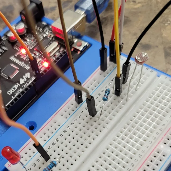
More than one LED
- One resistor per LED. LEDs wired side by side on a shared resistor don't share fairly: the one with the lowest forward voltage takes most of the current, and the brightness shifts as others switch on and off.
- An RGB LED is three LEDs in one. Give each color leg its own resistor, never one on the shared leg. The RGB LED article has the wiring.
- Pins have limits too. Each HERO Board pin is rated for 20 mA continuous, 40 mA absolute maximum, and the chip has an overall limit as well. A long row of bright LEDs is a job for a shift register or a transistor, not more pins.
Still dark after all that? It's rarely the resistor. My LED Won't Turn On checks the usual causes in two minutes, and the LED and Resistor articles cover the parts themselves.
Cogsworth City: HERO Starter Kit: Night 2 is this circuit: your first LED and resistor light a pirate ship's lantern. LEDs, an RGB LED, buttons and light sensors on the HERO Board, with 40 resistors in four values.
Python Starter Kit: Neon Realm: The 3.3 V side: red, yellow and green LEDs on a Raspberry Pi Pico WH, with resistors in four values and 20 lessons in MicroPython.
Questions
Can I use a 330 Ω resistor instead of 220 Ω?
Yes. A red LED on 5 V gets about 9 mA instead of 13.6 mA: a little dimmer, just as safe. 330 Ω is the other common choice for LEDs on 5 V boards.
Does the resistor go before or after the LED?
Either. In a single loop the same current flows through every part, so the resistor works on the pin side or on the ground side.
Do I need a resistor for the built-in LED on pin 13?
No. That LED is wired on the board with its own resistor. The resistor rule is for LEDs you add to the breadboard.
What happens if the resistor is too small?
Too much current flows. The LED runs hot and fails early, and with no resistor at all it often fails at once. The pin driving it can be damaged too.
Why is my LED so dim on a Raspberry Pi Pico?
At 3.3 V there's less voltage left over for the resistor, so a red LED behind 220 Ω gets about 6 mA instead of about 13 mA on a 5 V board. Blue and white LEDs are dimmer still, because their forward voltage takes almost all of the 3.3 V.