Build a keypad door lock with an OLED screen
Updated
A keypad lock is the project that makes a microcontroller feel like a real machine. You type four digits and a screen answers Open or Wrong. Behind that, the board is scanning sixteen buttons, building your guess one character at a time and comparing it with the code it keeps in memory.
Here is the whole build: a 16-button keypad, a small OLED screen and the HERO Board, joined by twelve jumper wires and no breadboard. The code is the one that passed its test in our simulator (typing 1, 2, 3, 4 printed Open), explained section by section, with three ways to take it further.
What you'll build and learn
The screen reads Locked. Each key you press adds a star, so nobody looking over your shoulder sees the digits. After the fourth key it says Open and Welcome back, or Wrong and Try again. Press * at any time to start over. Along the way you learn:
- Reading a matrix keypad with the Keypad library: 16 buttons on only 8 pins. The keypad article explains the row-and-column scan, and the Keypad library article lists its functions.
- Building a string from key presses in a
chararray, and comparing two strings withstrcmp(). - Drawing text on an OLED with U8g2, in a way that leaves room in the board's 2 KB of RAM. See OLED display and U8g2.
- I2C, the two-wire bus the screen talks on: I2C communication.
Run it: The keypad code lock, running · The finished build in the CraftingTable simulator: the same parts, wiring and code as this page.
Parts
| Part | How many | Notes |
|---|---|---|
| HERO Board | 1 | Uno-compatible, ATmega328P |
| 16-button keypad (4x4) | 1 | 8 pins: rows R1 to R4, columns C1 to C4 |
| OLED screen, 128x64, SH1106, I2C | 1 | 4 pins: GND, VCC, SCL, SDA |
| Jumper wires | 12 | 8 for the keypad, 4 for the screen |
| USB cable | 1 | Power and upload |
Every part here comes in 30 Days Lost in Space: the HERO Board, the keypad, the OLED screen, the jumper wires and the USB cable. Pandora's Box includes a 4x4 keypad too, and its own door-lock lesson answers on an LCD text screen instead.
Wiring
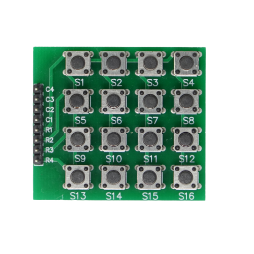
Twelve wires, each straight from a part to the board. The keypad needs no resistors: the library switches on the chip's own pull-up resistors.
| Part pin | HERO Board pin | What it carries |
|---|---|---|
| Keypad R1 | D5 | Row 1: keys 1, 2, 3, A |
| Keypad R2 | D4 | Row 2: keys 4, 5, 6, B |
| Keypad R3 | D3 | Row 3: keys 7, 8, 9, C |
| Keypad R4 | D2 | Row 4: keys *, 0, #, D |
| Keypad C1 | D6 | Column 1: keys 1, 4, 7, * |
| Keypad C2 | D7 | Column 2: keys 2, 5, 8, 0 |
| Keypad C3 | D8 | Column 3: keys 3, 6, 9, # |
| Keypad C4 | D9 | Column 4: keys A, B, C, D |
| OLED SDA | A4 | I2C data |
| OLED SCL | A5 | I2C clock |
| OLED VCC | 5V | Power |
| OLED GND | GND | Ground |
Rows run from D5 down to D2 and columns from D6 up to D9: the same pins as Day 11 of 30 Days Lost in Space.
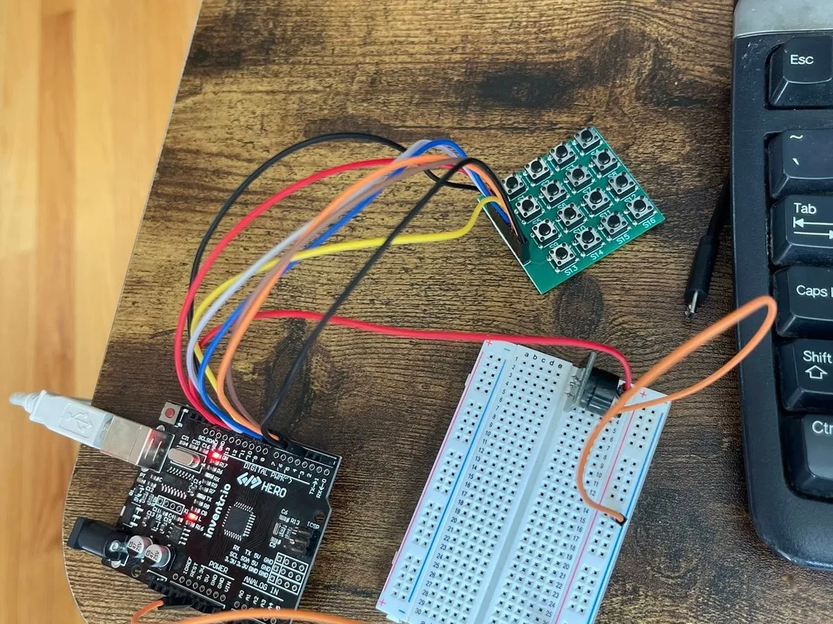
Two habits save most keypad builds. Count the header by the labels printed on the keypad, not by the order in a photo, and push every jumper all the way down. On the screen, go by the labels on its own header: the kit's screen reads GND, VCC, SCL, SDA from the left, and some screens put VCC first.
The code
Install two libraries from the Library Manager in the Arduino IDE first: Keypad by Mark Stanley and Alexander Brevig, and U8g2 by olikraus. Wire.h comes with the IDE. Then upload this sketch. The code that opens it is 1234.
// Keypad code lock: type the 4-digit code on the keypad; the screen says Open or Wrong.
#include <Keypad.h>
#include <U8g2lib.h>
#include <Wire.h>

const byte ROWS = 4;
const byte COLS = 4;
const char BUTTONS[ROWS][COLS] = {
  { '1', '2', '3', 'A' },
  { '4', '5', '6', 'B' },
  { '7', '8', '9', 'C' },
  { '*', '0', '#', 'D' }
};
const byte ROW_PINS[ROWS] = { 5, 4, 3, 2 };
const byte COL_PINS[COLS] = { 6, 7, 8, 9 };
Keypad keypad = Keypad(makeKeymap(BUTTONS), ROW_PINS, COL_PINS, ROWS, COLS);

// The page buffer (_1_) draws the screen in strips from 128 bytes of RAM; the whole frame (_F_) would take 1,024 of
// the board's 2,048 and leave too little for everything else.
U8G2_SH1106_128X64_NONAME_1_HW_I2C u8g2(U8G2_R0);

const char CODE[] = "1234";
char typed[5] = "";
byte count = 0;

void show(const char* top, const char* bottom) {
  u8g2.firstPage();
  do {   // the screen is drawn in 8 strips: this runs once for each
    u8g2.setFont(u8g2_font_ncenB14_tr);
    u8g2.drawStr(0, 24, top);
    u8g2.drawStr(0, 54, bottom);
  } while (u8g2.nextPage());
}

void setup() {
  Serial.begin(9600);
  u8g2.begin();
  show("Locked", "Code: ");
}

void loop() {
  char key = keypad.getKey();
  if (!key) return;
  if (key == '*') {           // * starts over
    count = 0;
    typed[0] = 0;
    show("Locked", "Code: ");
    return;
  }
  typed[count++] = key;
  typed[count] = 0;
  char stars[12] = "Code: ";
  for (byte i = 0; i < count; i++) strcat(stars, "*");
  show("Locked", stars);
  if (count == 4) {
    bool right = strcmp(typed, CODE) == 0;
    Serial.println(right ? "Open" : "Wrong");
    show(right ? "Open" : "Wrong", right ? "Welcome back" : "Try again");
    count = 0;
    typed[0] = 0;
  }
}How the code works
The keypad map
BUTTONS is a 4 by 4 grid of characters laid out like the keys themselves. ROW_PINS and COL_PINS tell the library which board pin each row and column is on, and makeKeymap() hands it all to the Keypad object. The library does the scanning: it pulls one row low at a time and reads the four columns, so a pressed key shows up as the one place where its row and column meet. A full scan takes well under a millisecond.
The screen and its page buffer
The long constructor names the screen exactly: an SH1106 chip, 128 by 64 pixels, on the hardware I2C pins. The _1_ in it picks the page buffer. A full frame of this screen takes 1,024 bytes, half of the board's 2,048 bytes of RAM. The page buffer draws it in eight strips from 128 bytes instead, which is why show() draws inside a do { } while (u8g2.nextPage()) loop: the same drawing runs once per strip. Compiled, this sketch keeps 1,044 bytes of RAM in use; with the full frame it would leave barely 100 bytes for everything else.
In drawStr(x, y, text), y is the baseline, the bottom of the letters. That's why the first line is drawn at 24 and not 0: at 0 the text would sit above the top of the screen.
Collecting the code
getKey() never waits. It returns a key once, at the moment it's pressed, and 0 the rest of the time, so if (!key) return; simply ends this pass of loop() until a new key arrives. A real key goes into typed, a char array of five: room for four characters plus the 0 that marks where a C string ends. count says how many have been typed. The bottom line is then rebuilt as Code: followed by one star per key, joined on with strcat().
The check
On the fourth key, strcmp(typed, CODE) compares the two strings character by character and returns 0 when they match. The board prints Open or Wrong to the Serial Monitor (that line is what the simulator's test listened for), shows the answer on the screen and empties typed for the next try. Every key counts as a character, letters and # included; only * is special.
Try it without parts
The keypad and the OLED are both parts in the free browser simulator. Add them to a HERO Board, wire them as in the table, paste the code and press Run, then click the keys on screen. The simulator emulates the board's chip, so the same sketch runs unchanged when you build it for real.
Make it yours
- Change the code. Edit the
CODEline. Keep it four characters, or change the 4 incount == 4to your length and maketypedone longer than the code. - Beep on every key. Wire a passive buzzer's S pin to D10 and its minus pin to GND, then add
tone(10, 880, 100);on the line afterif (!key) return;.tone()returns at once, so the beep never slows the keypad: see tone() and noTone(). Day 13 of 30 Days Lost in Space gives its security panel the same 880 Hz beep. - Lock out after three wrong tries. Count wrong answers in a variable. After the third, show Locked out and ignore the keypad for 30 seconds, timed with millis() so the board stays responsive. Keeping track of locked, typing and locked-out is your first state machine.
Common problems
- The wrong keys come out. Add
Serial.println(key);under thegetKey()line and press 1, the top left key. If it prints A, the column wires are in backwards; *, the row wires are; D, the whole header is turned round; 2 or 4, a wire is one pin off. If A prints *, rows and columns are swapped. - A whole row or column is dead. One wire is loose. Which keys fail tells you which wire: four keys across is a row wire, four keys down is a column wire.
- The screen stays black. SDA and SCL are swapped (SDA goes to A4, SCL to A5), VCC and GND are swapped, or the screen answers at address 0x3D instead of 0x3C. The blank OLED checklist goes through each.
- A stripe of noise or a shifted picture. Your screen has an SSD1306 chip, not an SH1106. Change
SH1106toSSD1306in the constructor line. - Keypad.h: No such file or directory. The library isn't installed. Install Keypad from the Library Manager and upload again. Other compile errors: syntax errors.
30 Days Lost in Space: The HERO Board, this keypad, the OLED screen, a 4-digit display, a buzzer and more, with filmed lessons that build a passcode lock and the security panel after it.
Questions
How do I change the code on a keypad lock?
Change the text in the CODE line of the sketch and upload it again. The sketch checks after exactly four keys, so keep four characters, or change the 4 in count == 4 and make the typed array one longer than your code.
Does a 4x4 keypad need resistors?
No. The Keypad library turns on the board's internal pull-up resistors, so each of the eight wires goes straight from the keypad to a pin.
Can this open a real door?
The board knows when the code is right, and the line that prints Open is where you would drive a servo or a relay to move a latch. That takes an extra part with its own power, and a sketch like this is a learning project, not a security product, so keep a key.
Will a membrane keypad work instead?
Yes. A flat membrane keypad has the same four rows and four columns on eight pins, so the code is unchanged. Find which pin is which row and column from its labels or its seller's diagram, then wire it to the same board pins.