KY-036 touch sensor module: wiring, code and calibration
Updated
The KY-036 turns a fingertip into a switch. Touch the bare metal at its end and its D0 pin goes high; with a few lines of code, one touch turns a light on and the next turns it off.
It looks like the other red boards in the kit and shares their comparator and trim pot, but it's the odd one out. You calibrate it differently, you read it differently, and it's easy to wire wrong: the instructor fried his first one in the walkthrough. Here's how to get yours right the first time.
What's on the board
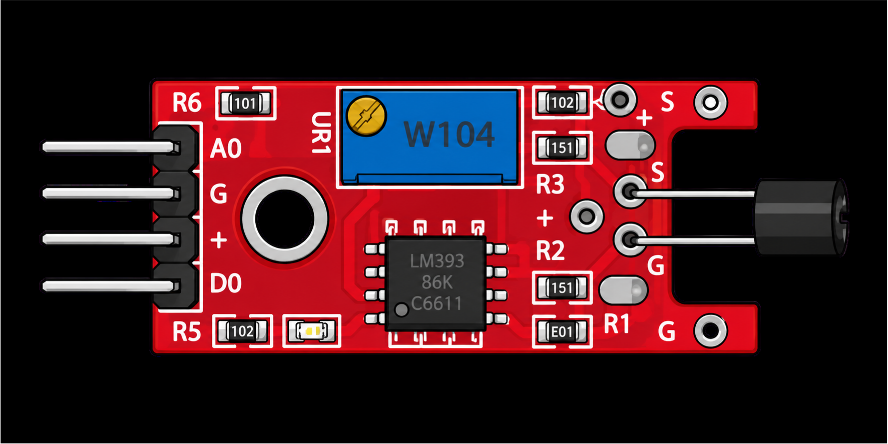
- The touch sensor: the black three-legged part at the end of the board, with the small metal lead you touch.
- An LM393 comparator, the 8-legged chip, which turns a touch into an on or off on D0.
- A blue trim pot (marked 104) that sets how much it takes to trip.
- A 4-pin header: A0, G (ground), + (5 V) and D0.
Your finger on the lead changes the signal going into the comparator, and when the change is big enough, D0 switches. The course's notes are honest about its limits: it isn't very sensitive and may need a firm touch. If you need something lighter, a capacitive touch module is the better tool.
Wiring the KY-036 to the HERO Board
| KY-036 pin | HERO Board | What it carries |
|---|---|---|
| A0 | Not used | Stays near 1023 on 5 V |
| G | GND | Ground |
| + | 5V | Power |
| D0 | Pin 8 | 1 while touched |
Look at the order on the header: A0, G, +, D0. Ground and 5 V sit side by side in the middle, so one wire slipped by one pin swaps power and ground. That's how the walkthrough's first module was lost, and why the second was wired very carefully. Check G and + twice before you plug in the USB cable.
The course's sketch ignores A0. Its tests found A0 sits at about 1023 on 5 V whether you touch the sensor or not, so everything you need is on D0. In the walkthrough the touch signal goes to pin 3; the code below uses 8. Match the wire to the number in your sketch.
The course also adds an external LED on pin 13 with a 330 Ω resistor to ground, alongside the board's built-in LED, so every touch is easy to see from across the room.
Calibrate it: the click method
This trim pot has no obvious middle, so the course finds its end stop and counts back from there:
- Turn the screw clockwise until you hear a faint click. You've just gone past maximum sensitivity, to the end of the pot's travel.
- Keep turning and the click repeats about every turn and a half. That confirms you're at the end.
- Now turn it back two full turns counter-clockwise.
Run the sketch below. The LED should be off. Touch the lead and it comes on; touch it again and it goes off. If nothing happens, try another half turn either way and press a little more firmly.
The code: one touch on, the next touch off
No library needed. This is the course's sketch, shortened. It flips a flag between -1 and +1 on every touch and sets the LED from it:
const uint8_t KY_036_DIGITAL_IN = 8;  // D0
int KY_036_Flag = -1;                 // -1 = LED off, +1 = LED on

void setup() {
  Serial.begin(9600);
  pinMode(LED_BUILTIN, OUTPUT);
  pinMode(KY_036_DIGITAL_IN, INPUT);
}

void loop() {
  int ky036_Dval = digitalRead(KY_036_DIGITAL_IN);
  if (ky036_Dval == HIGH) {             // touch detected
    KY_036_Flag = KY_036_Flag * -1;     // flip between -1 and +1

    if (KY_036_Flag > 0) {
      digitalWrite(LED_BUILTIN, HIGH);
    } else {
      digitalWrite(LED_BUILTIN, LOW);
    }
    delay(250);   // the sensor bounces: only count the first touch
  }
}Multiplying by -1 is a neat trick: it flips the sign every time, so the flag alternates without an if. The delay(250) is there because D0 doesn't give one clean edge per touch. It chatters, and in the walkthrough you can see the LED flicker. Waiting a quarter of a second skips the chatter.
There's a catch. Hold your finger on the lead and the sketch sees a new touch every 250 ms, so the LED blinks on and off for as long as you hold. Tap, don't hold. Or use this version, which counts a touch only after the sensor has been quiet for half a second:
const uint8_t KY_036_DIGITAL_IN = 8;  // D0
bool ledOn = false;
unsigned long lastTouch = 0;

void setup() {
  pinMode(LED_BUILTIN, OUTPUT);
  pinMode(KY_036_DIGITAL_IN, INPUT);
}

void loop() {
  if (digitalRead(KY_036_DIGITAL_IN) == HIGH) {
    if (millis() - lastTouch > 500) {   // quiet for half a second: a new touch
      ledOn = !ledOn;
      digitalWrite(LED_BUILTIN, ledOn ? HIGH : LOW);
    }
    lastTouch = millis();               // still touching: push the window back
  }
}Every time D0 reads high, lastTouch moves forward, so a finger that stays put never opens the half-second gap. The LED changes only when a touch begins after a real pause. The same pattern tames any jittery switch; the Help Center's debouncing article explains it in depth, and millis() timing covers the clock it uses.
What to build with it
- A secret chest. The walkthrough's own idea: hide the lead somewhere only you know to touch, and use it to unlock something.
- A touch lamp. One touch on, one touch off, with an LED or the kit's KY-016 RGB LED.
- A touch counter. Count touches and show the total in the Serial Monitor or on a display.
- A don't-touch alarm. Sound the KY-012 buzzer the moment someone touches the lead.
Common problems
- The module got hot or stopped working. G and + were swapped. They're the two middle pins; check them before you power up.
- Nothing happens on a touch. Redo the click calibration, press firmly, and make sure D0 goes to the pin your code reads.
- The LED blinks while you hold your finger on it. The course's sketch counts a new touch every 250 ms. Use the version above.
- A0 never changes. That's expected on this board. Read D0.
Watch it
The KY-036 walkthrough is lesson 28 of the SensorKit course. The red board it shares with the KY-026 flame sensor and the KY-037 behaves differently there, and every module in the 37-in-1 sensor kit covers the rest. The digital I/O article explains digitalRead().
37-in-1 Sensor Kit: The KY-036 and 36 more modules in a latching case, with the free SensorKit course: 31 filmed walkthroughs and example code.
HERO Board: The Uno-compatible board the SensorKit walkthroughs are built around, with its USB cable.
Questions
How does the KY-036 touch sensor work?
Your finger on its metal lead changes the signal going into the module's LM393 comparator, which switches the D0 pin high. The trim pot sets how big a change it takes.
Why doesn't the KY-036's analog pin change?
In the SensorKit course's tests A0 sat at about 1023 on 5 V whether the sensor was touched or not. The touch shows up on D0, so read that.
Why does my LED flicker when I touch the KY-036?
D0 chatters during a touch. Ignore new touches for a moment after each one: the course's sketch waits 250 ms, and the version on this page waits for a half-second pause.
How do I adjust the KY-036's sensitivity?
Turn the trim pot clockwise until it clicks at the end of its travel, then turn it back two full turns. Fine-tune from there in half turns.