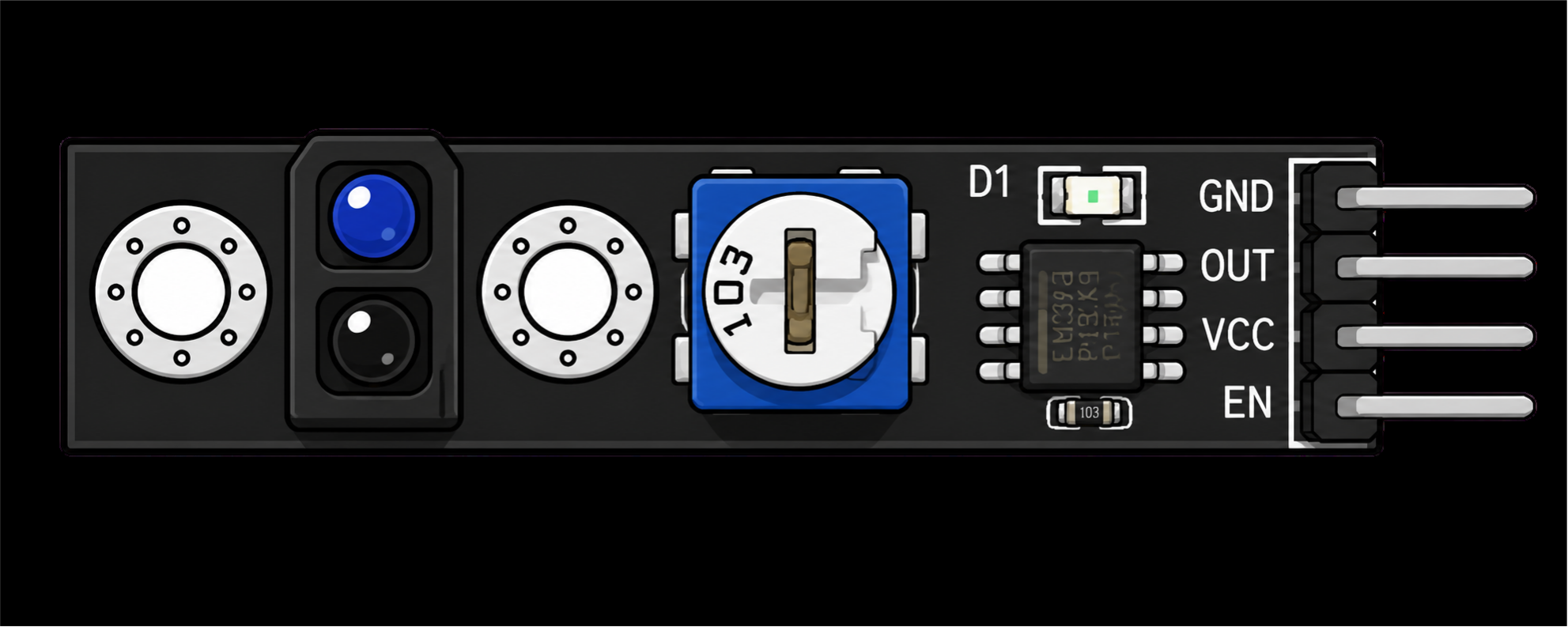
KY-033 line tracking sensor module: how it works, wiring and code
Updated
The KY-033 is how a line-following robot sees the line. At one end of the board an infrared LED and a light sensor sit side by side, facing the floor. A white floor bounces the light back; a black line soaks it up. The module turns that difference into a single on/off signal.
One KY-033 tells you whether it's over the line. Two side by side tell a robot which way to steer, and that's the whole secret of line following.
How it works
The infrared LED shines down all the time. Over a light surface, plenty of that light reflects into the sensor; over black tape or ink, very little does. A comparator on the board checks the amount against a set point, which you adjust with the blue knob, and switches the output.
In the walkthrough, the module's own indicator light was on over white and went dark over the black line. On the signal pin, the simulator's model of this module reads LOW over a light floor and HIGH over a dark line, so with the course sketch below, the board's L LED lights when the sensor is over the line. Check yours the same way: print the pin and slide the module over a strip of black tape.
It works close up. The further it sits from the surface, the less light comes back and the harder it is to tell black from white, so mount it just above the floor.
Wiring
Check the labels before you wire. The instructor has seen this module in more than one version: one printed GND, OUT, VCC, another printed G, V+, S. They're the same three connections in a different order, so wire by the letters on your board, not by position. The simulator's drawing at the top of this page shows a fourth pin, EN; the board in the kit has three.
| Label on your module | HERO Board pin | What it carries |
|---|---|---|
| GND or G | GND | Ground |
| VCC or V+ | 5V | Power |
| OUT or S | 8 | The signal |
Pin 8 matches the course sketch.
The code from the course
const int trackPin = 8;   // the module's OUT (or S) pin
const int ledPin = 13;    // the board's L LED

void setup() {
  pinMode(trackPin, INPUT);
  pinMode(ledPin, OUTPUT);
}

void loop() {
  int val = digitalRead(trackPin);
  if (val == HIGH) {
    digitalWrite(ledPin, HIGH);
  } else {
    digitalWrite(ledPin, LOW);
  }
}Make a test strip before anything else: a line of black electrical tape on white paper. Slide the module across it and watch the L LED and the module's own light swap over as it crosses.
Setting the knob
The blue knob moves the comparator's set point. Hold the module at the height it will ride at, over the white paper, and turn the screw until the indicator just comes on. Then move over the tape and check it goes out. If it stays on over black, turn back a little; if it won't come on over white, turn the other way or bring the module closer to the surface.
From one sensor to a line follower
One sensor can only say 'on the line' or 'off it'. When it says 'off', it can't tell you which side you drifted to. That's why line-following robots use at least two, one each side of the line:
| Left sensor | Right sensor | What the robot does |
|---|---|---|
| Over white | Over white | The line is between them: drive straight |
| Over black | Over white | Drifted right: steer left |
| Over white | Over black | Drifted left: steer right |
| Over black | Over black | A crossing or the end: stop, or decide |
The usual two-sensor rule, with the sensors placed just either side of the line.
In code that's two digitalRead() calls and an if / else if chain, which the if/else article covers. Each KY-033 needs its own input pin; 7 and 8 make a good pair, since the course's pin notes recommend 4, 7 or 8 for simple inputs.
Line tracker or obstacle sensor?
The KY-032 obstacle sensor uses the same kind of infrared light but points forward and reaches further, to see objects in the way. The KY-033 points down and works up close, to read what's printed on the surface. The kit's third infrared module, the KY-010 light blocking module, shines across a slot instead.
What to build with it
- A line-following robot, with two modules and two motors. It's the use the walkthrough calls out.
- An edge detector for a table-top robot. Over the edge of the table, no light comes back at all, so the sensor reads as if it's over black: stop and back up.
- A stripe counter. Count black marks on a turning wheel or a moving belt, the same edge-counting idea as the photo interrupter counter.
Common problems
- It reads the same over black and white. The knob is off, or the module is too high. Lower it toward the surface and set the knob again.
- It changes with the room lighting. Sunlight and some lamps carry infrared. Shade the sensor, or test away from the window.
- Nothing works at all. Check the labels again. The pin order varies between versions, and VCC on the wrong pin won't power it.
- Shiny black tape reads as white. Glossy surfaces can bounce infrared back even when they look dark. Use matte tape or a printed line.
Watch it on the bench
The KY-033 walkthrough in the free SensorKit course wires the module to pin 8 of a HERO Board and passes it over white and black, in under three minutes. The 37-in-1 sensor kit guide covers every other module in the case.
37-in-1 Sensor Kit: The KY-033 line tracker, the KY-032 obstacle sensor and 35 more modules, with the free SensorKit course.
HERO Board: The Uno-compatible board the walkthroughs are filmed on. A spare means a robot can keep its own board.
Questions
How does the KY-033 line tracking sensor work?
An infrared LED shines at the surface and a sensor measures how much light comes back. White reflects a lot and black very little; a comparator turns that into a digital output, with a knob to set where it switches.
Is the KY-033 output HIGH or LOW over a black line?
HIGH over a dark line and LOW over a light surface, as the simulator models it; on the course's bench the module's indicator light was on over white. Check yours by printing the pin over a strip of black tape.
How many KY-033 sensors does a line follower need?
At least two, one each side of the line, so the robot knows which way it drifted. One sensor can only tell you that it has left the line, not which way.
Why are the pin labels on my KY-033 different?
The module is made in more than one version. The course's instructor has seen GND, OUT, VCC on one and G, V+, S on another. Wire by the labels, not by position.
Will the course code run on an Arduino Uno?
Yes. It's standard Arduino code, and the HERO Board is Uno-compatible, so the sketch and the pin numbers are the same.