KY-027 magic light cup module: how it works, wiring and code
Updated
The KY-027 is the kit's party trick. Each module holds a tilt switch and an LED, and the kit gives you two. Wire both to your board, tip them like a pair of cups, and the light seems to pour from one into the other.
Behind the trick is a tidy lesson in reading an input and driving an output at once, with one shared number linking the two cups. Here's how the module works, how to wire a pair, and what each line of the SensorKit code does.
A tilt switch and an LED on one board
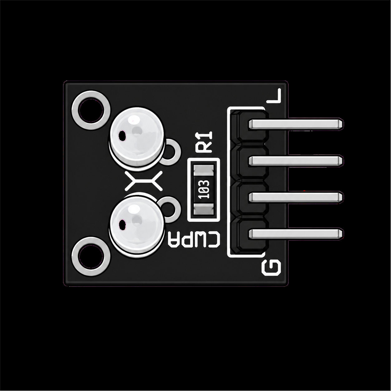
The switch is a small sealed tube with a bead of mercury inside, as the walkthrough shows. Tip the module one way and the bead rolls across two contacts and closes the switch; tip it back and it rolls off and opens it. The board reports that on its S pin as HIGH or LOW. The resistor marked 103 (10,000 ohms) holds S at a steady level while the switch is open, so the pin never floats.
The LED is wired separately: its L pin goes to a PWM pin, so your code sets its brightness with analogWrite() instead of only switching it. The other two pins are power: + to 5V and G to ground. Reading along the header, the walkthrough calls them G, +, S and L.
Mercury is toxic, but sealed in its tube it can't reach you. Don't bend the switch hard or squeeze it. If one ever cracks, don't touch it: an adult should clean it up the way you'd deal with a broken mercury thermometer, following local guidance.
Wiring a pair
| KY-027 pin | Cup A | Cup B |
|---|---|---|
| L (LED) | D9 | D6 |
| S (tilt switch) | D8 | D7 |
| + | 5V | 5V |
| G | GND | GND |
From the SensorKit lesson's code. D9 and D6 are PWM pins (marked ~), which the LEDs need; the switch pins can be any digital pin.
Two modules means four power wires, so run 5V and GND to the breadboard's rails and feed both cups from there. The walkthrough's instructor squeezed the two side by side and found the breadboard tight. Space them apart and the wiring is easier, and so is tilting them.
The code: one number, two cups
int ledPinA = 9;
int switchPinA = 8;
int switchStateA = 0;
int ledPinB = 6;
int switchPinB = 7;
int switchStateB = 0;
int brightness = 0;

void setup() {
  pinMode(ledPinA, OUTPUT);
  pinMode(ledPinB, OUTPUT);
  pinMode(switchPinA, INPUT);
  pinMode(switchPinB, INPUT);
}

void loop() {
  switchStateA = digitalRead(switchPinA);
  if (switchStateA == HIGH && brightness != 255) {
    brightness++;
  }
  switchStateB = digitalRead(switchPinB);
  if (switchStateB == HIGH && brightness != 0) {
    brightness--;
  }
  analogWrite(ledPinA, brightness);        // cup A shows brightness
  analogWrite(ledPinB, 255 - brightness);  // cup B shows the rest
  delay(20);
}Everything hangs on brightness. Cup A shows it and cup B shows 255 - brightness, so the two always add up to full: as one fills, the other empties.
- Every 20 ms the loop reads both switches. If A's reads HIGH,
brightnessgoes up one step; if B's reads HIGH, it goes down one. - When both switches read the same, the step up and the step down cancel, and the light stays where it is. It only flows when the cups disagree, at one step per 20 ms: about five seconds to move all the way from one cup to the other.
- The
!= 255and!= 0checks stopbrightnessat the ends, so it never runs past full or below off. - The switch pins use plain
INPUT, notINPUT_PULLUP, because the module's own 10k resistor already holds S steady.
In the KY-027 walkthrough, tilting the pair drains the light from the higher cup into the lower one, like water. If yours flows uphill, swap the two switch pin numbers (8 and 7) in the code.
Build on it
- Change the pour.
delay(20)sets the speed: 40 makes the full pour take about ten seconds, 5 makes it just over one. - A tilt alarm. One cup is enough: read its S pin and sound the KY-012 active buzzer when it tips over, with the cup's own LED as the warning light.
- A level. The walkthrough suggests it: mount a cup on something that should stay flat, and the switch tells you the moment it leans.
When it doesn't work
- The light never moves. Both switches read the same all the time. Add
Serial.begin(9600);tosetup(), printswitchStateAandswitchStateB, and tilt each cup: each value should change. - One LED never lights. Its L wire is on a pin without PWM, or it's a row off on the breadboard.
- It flows the wrong way. Swap 8 and 7 in the code.
- The light flickers while a cup is tilted. The mercury bead is sitting right at the edge of its contacts and bouncing. Tilt further.
The KY-027 is a part in the free browser simulator: click the module while the sketch runs to tilt it. For a switch you press rather than tip, see the KY-004 button, and for every other module in the case, the 37-in-1 sensor kit guide.
37-in-1 Sensor Kit: Two KY-027 light cups and the rest of the 37 modules in a latching case, with the free SensorKit course.
HERO Board: The Uno-compatible board every SensorKit walkthrough is filmed on, with its USB cable.
Questions
What is the KY-027 magic light cup?
A module with a tilt switch and an LED on one board. With two of them, code can pass brightness from one cup's LED to the other's as you tilt them, so the light seems to pour between the cups.
Does the KY-027 contain mercury?
The modules in the SensorKit walkthrough use a small sealed mercury switch. It's safe while sealed; don't bend or crush it, and if one breaks, have an adult clean it up following local guidance.
What are the KY-027's four pins?
L drives the LED (use a PWM pin), S is the tilt switch's signal, + goes to 5V and G to ground.
Can I use one KY-027 on its own?
Yes. Read S with digitalRead() as a tilt switch, and drive L as an LED. The two-cup sketch is just the most striking way to use a pair.