KY-025 reed switch module: how it works, wiring and code
Updated
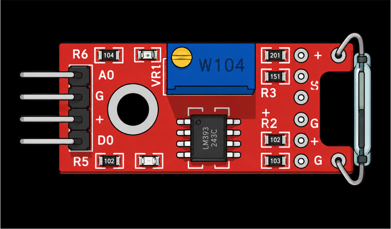
Look at the end of the KY-025 and you'll see a small glass tube with a wire leaving each end. Inside are two thin metal reeds that almost touch. Bring a magnet close and the reeds become magnets themselves, pull together and close the circuit. Take the magnet away and they spring apart.
It's the kind of switch hidden in the magnetic contacts on doors and windows in many alarm systems. On this module it sits on a red comparator board, which gives you a digital pin, an analog pin and a knob. Here's what each one tells you, and how the course's instructors tuned it on the bench.
What's on the board
- The reed switch in its glass tube. It's a real mechanical switch: the reeds physically move. Either pole of a magnet closes it.
- An LM393 comparator that turns the switch's voltage into a clean digital output.
- A blue trim pot that sets where the digital output trips.
- Two LEDs: LED1 shows power; LED2 lights when the threshold is crossed.
- Four pins: A0 (analog), G (ground), + (5 V) and D0 (digital).
It's one of seven red boards in the kit built the same way. The course's code notes list them: the KY-024 linear Hall, KY-025 reed switch, KY-026 flame, KY-028 digital temperature, KY-036 touch, and the KY-037 and KY-038 sound sensors. The notes say they all work the same way and use the same code with different names, so learning this one teaches you all seven.
Wiring
| Module pin | HERO Board pin | What it carries |
|---|---|---|
| A0 | A0 | The analog value, 0 to 1023 |
| G | GND | Ground |
| + | 5V | Power |
| D0 | 8 | 1 when a magnet is detected |
Pins from the course sketch. The filmed walkthrough wires D0 to pin 3; either works as long as the code matches.
The code from the course
The course sketch reads both pins and lights the L LED when D0 reports a magnet. Its print lines ship commented out; they're switched on here, because you need them to set the knob.
const uint8_t KY_025_DIGITAL_IN = 8;   // the module's D0 pin
const uint8_t KY_025_ANALOG_IN = A0;   // the module's A0 pin

void setup() {
  Serial.begin(9600);
  pinMode(LED_BUILTIN, OUTPUT);
  pinMode(KY_025_DIGITAL_IN, INPUT);
  pinMode(KY_025_ANALOG_IN, INPUT);
}

void loop() {
  int ky025_Dval = digitalRead(KY_025_DIGITAL_IN);
  int ky025_Aval = analogRead(KY_025_ANALOG_IN);

  if (ky025_Dval == HIGH)               // magnetic field detected
    digitalWrite(LED_BUILTIN, HIGH);
  else                                  // no magnetic field
    digitalWrite(LED_BUILTIN, LOW);
  delay(150);                           // how often to check

  Serial.print("Digital Value: ");
  Serial.print(ky025_Dval);
  Serial.print(" | ");
  Serial.print("Analog value: ");
  Serial.println(ky025_Aval);
}What the numbers mean
The course's bench notes for this board describe what to expect, and the analog side reads backwards at first:
- No magnet: Digital 0, Analog 1023.
- Magnet near: the analog value drops below 1023. Once it falls below about 510, D0 flips to 1 and LED2 lights.
- Stronger signal, lower number. That's true on all seven red boards: closer to 0 means more.
The notes also call the KY-025 an all-or-nothing sensor. The reeds are either together or apart, so read it as 'magnet or no magnet', not as a distance gauge. If you need to know how strong a field is, or which pole is facing the sensor, that's the job of the KY-024 linear Hall.
Tuning the trim pot
This is the course's calibration routine, step by step:
- Upload the sketch above and open the Serial Monitor at 9600 baud. With no magnet nearby you should see
Digital Value: 0 | Analog value: 1023. - Hold the magnet at the distance where you want the switch to trigger. The analog value should drop below 1023.
- Turn the brass screw on the blue pot. Clockwise lowers the analog value; counterclockwise raises it. When it falls below about 510, D0 changes from 0 to 1.
- Fine-tune by watching LED2 on the module. When it lights, you've crossed the threshold. Adjust until the trigger happens at the same point every time you bring the magnet in.
Be patient with the screw. The blue box-shaped trimmer on these boards is a multi-turn part, so a quarter turn can change nothing at all. Keep going in one direction before you decide it isn't working.
Reed switch or Hall sensor?
A reed switch is a real contact: any magnet pole closes it, and the switch itself needs no power (on this module, it's the comparator that does). A Hall sensor is solid-state, with nothing to move or wear out, and it reacts faster. The KY-003 Hall sensor is the Hall equivalent of this module's digital pin, with no knob to set. The KY-024 adds strength and polarity. For a door alarm any of the three will do; for counting a fast-spinning wheel, a Hall sensor is the better choice.
What to build with it
- A door or window alarm. Module on the frame, magnet on the door. Shut, D0 reads 1; open, it reads 0. Sound a buzzer on the change. This is the first use the course's notes give.
- A wheel counter. A magnet on the rim closes the switch once per turn. Count the moments D0 changes from 0 to 1.
- A secret latch. Hide the module inside a box and only open it when a magnet is held to the right spot on the outside.
Common problems
- D0 never changes. The trip point is past what your magnet reaches. Hold the magnet close and turn the screw until LED2 lights.
- LED2 is always on. The trip point is set too far the other way. Turn the screw back until it goes out with no magnet nearby.
- The analog value never leaves 1023. The reeds aren't closing. Bring the magnet closer and move it along the length of the glass, not just past one end.
- The glass is cracked. Reed switches are fragile. Never bend the legs right where they leave the glass.
Watch it on the bench
The KY-025 walkthrough in the free SensorKit course wires the module to a HERO Board and closes it with a fridge magnet, in under two minutes. The 37-in-1 sensor kit guide covers the other six red boards and everything else in the case.
37-in-1 Sensor Kit: The KY-025 and the other six red comparator boards, plus 30 more modules and the free SensorKit course.
HERO Board: The Uno-compatible board every SensorKit walkthrough is filmed on, with its USB cable.
Questions
How does the KY-025 reed switch work?
Two metal reeds sit in a sealed glass tube. A magnet nearby magnetizes them so they pull together and close the circuit; without it they spring apart. The board's comparator turns that into a digital output, and there's an analog output too.
Why is the KY-025's analog value 1023 with no magnet?
That's its resting reading. On all seven of the kit's red boards a stronger signal gives a lower analog value, and the digital pin flips to 1 when it falls below about 510.
What does the blue knob on the KY-025 do?
It sets where the digital pin trips. With a magnet at your chosen distance, turn the screw until LED2 on the board lights. Clockwise lowers the analog value; counterclockwise raises it.
Should I use a reed switch or a Hall sensor?
A reed switch is a simple contact that either pole of a magnet closes. A Hall sensor has no moving parts and reacts faster. For a door alarm either works; for counting a fast wheel, use a Hall sensor like the KY-003.