KY-019 relay module: how it works, wiring, code and safety
Updated
A pin on your board can light an LED, but it can't run a motor, a pump or a strip of lights. The KY-019 bridges that gap. Your code switches a small electromagnet; the electromagnet flips a real mechanical switch; and that switch opens or closes a completely separate circuit with its own power.
You can hear it work: every time the pin changes, the relay clicks. Here's what each part of the board does, how to wire the control side and the switched side, the SensorKit course's code, and the rule that matters most: as a beginner, switch low-voltage things only.
An electromagnet that throws a switch
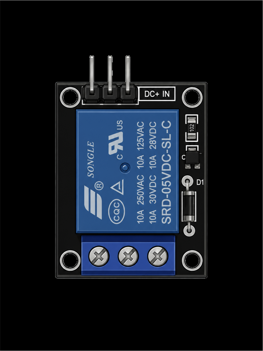
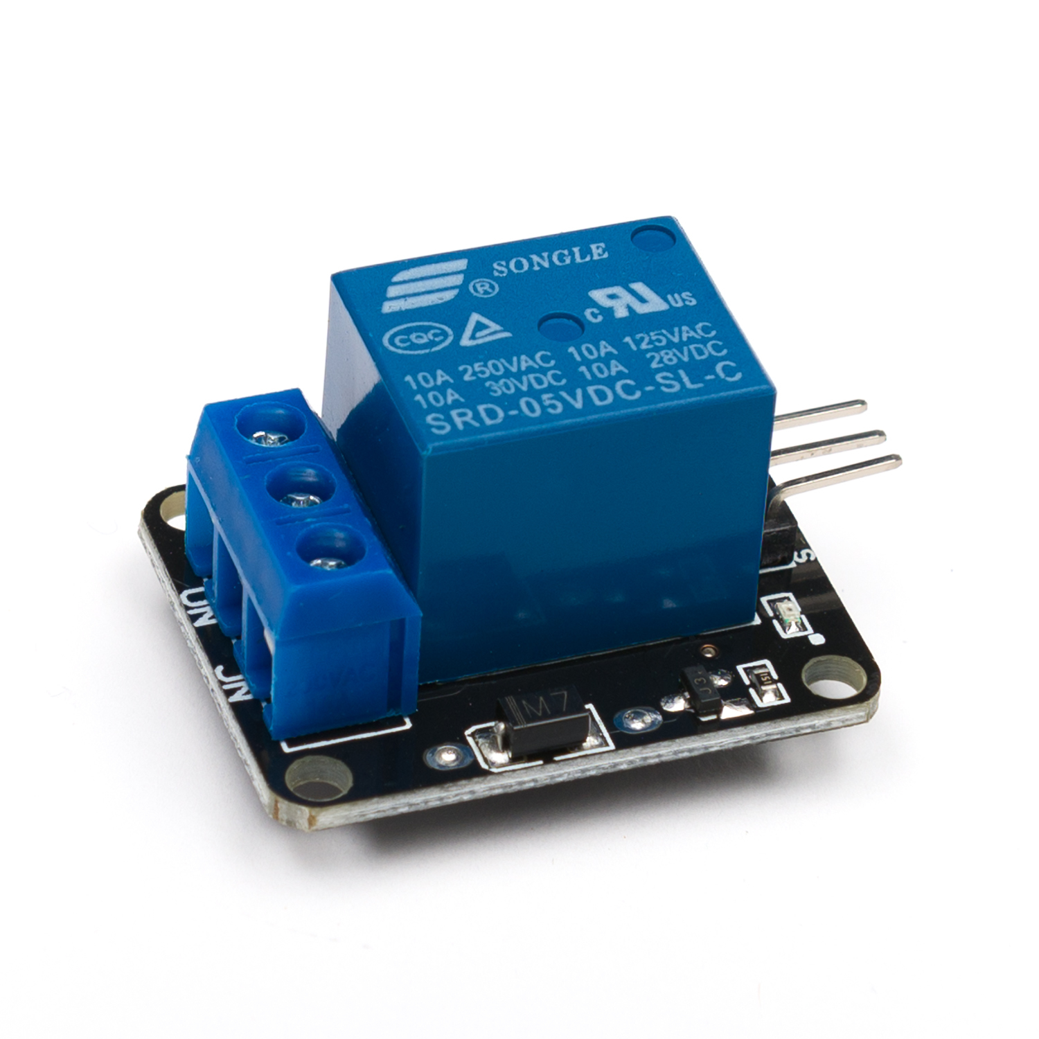
The blue box is the relay, a Songle SRD-05VDC-SL-C. The 05VDC in the name is its coil voltage: it switches on 5 V, which is why it suits a 5 V board like the HERO Board. Inside is a coil of wire around an iron core and a springy metal arm. Current through the coil turns it into a magnet, the arm snaps across, and the contacts change over. Cut the current and the spring pulls the arm back. That movement is the click.
Your pin can't power that coil by itself: a HERO Board pin should never supply more than 40 mA, and a relay coil wants more. So the module adds a small transistor that takes the coil's current from the 5V pin while your signal only switches it, a resistor marked 102 (1,000 ohms) that limits what flows from your pin, and a diode, D1. When a coil switches off, its collapsing magnetic field kicks back a spike of voltage; the diode gives that spike a harmless path so it never reaches the transistor. There's also a small LED that lights while the relay is on, which the walkthrough points out is handy when troubleshooting.
Two sides: control and switched
| Terminal | Side | Connect to |
|---|---|---|
| S | Control | D10, the lesson's pin |
| Middle pin (+) | Control | 5V |
| − | Control | GND |
| COM | Switched | One end of the break in your load's circuit |
| NO | Switched | The other end, if the load should run while the relay is on |
| NC | Switched | The other end instead, if the load should run while the relay is off |
Control pins from the SensorKit lesson's code and walkthrough. The switched side is a separate circuit with no electrical connection to your board.
COM (common) is always joined to one of the other two terminals. At rest, with S LOW, it touches NC (normally closed). Set S HIGH and the click moves it across to NO (normally open). Wire your load through COM and NO and it runs only while your code says so.
Picture the load's own circuit: its power supply, a wire to the load, the load, and a wire back. Break one of those wires and land the two ends on COM and NO. The relay is now a switch in that wire, and nothing on that side touches your HERO Board. That separation is what protects your board.
What to switch, and what never to
The relay's case is printed with ratings up to 10A 250VAC. Those are the limits of the relay part, not an invitation. A small open board like this has bare solder joints on the underside and screw terminals a finger can touch, and a mistake at wall voltage can kill.
- Switch only low-voltage DC with this module: a battery pack, a USB-powered fan or light, a small motor or an LED strip on its own supply.
- Never connect anything that plugs into a wall outlet. Mains wiring is a job for a qualified electrician and an enclosed, certified relay unit, not an open module on a breadboard bench.
- Give the load its own power supply. Never run a motor or a light strip from the HERO Board's 5V pin.
The code
int relay = 10;   // the relay's S pin: HIGH switches it on

void setup() {
  pinMode(relay, OUTPUT);
}

void loop() {
  digitalWrite(relay, HIGH);  // coil on: COM joins NO
  delay(1000);
  digitalWrite(relay, LOW);   // coil off: COM back to NC
  delay(1000);
}The KY-019 is active high, as the lesson's code notes: HIGH turns it on. One second on, one second off, a click each way, and the LED follows. Nothing is connected to the screw terminals yet, and that's the right first test: get the clicks and the LED working before any load goes on the other side.
Two habits to keep. Drive a relay with digitalWrite(), never analogWrite(): the contacts can't follow PWM, so they chatter and wear. And don't switch it faster than you need to, because every click wears the contacts a little.
Build a thermostat fan
The classic relay build reads a temperature and switches a fan. The kit has the sensor: the KY-015 reports temperature on one data pin through the DHT sensor library by Adafruit (install it from the Library Manager). This sketch turns the fan on above 26 degrees C and off below 24:
#include "DHT.h"

#define DHT_PIN 7          // KY-015 data pin
#define DHT_TYPE DHT11
const int RELAY_PIN = 10;  // KY-019 S

const float ON_ABOVE = 26.0;   // fan on above this (degrees C)
const float OFF_BELOW = 24.0;  // fan off below this

DHT dht(DHT_PIN, DHT_TYPE);
bool fanOn = false;

void setup() {
  pinMode(RELAY_PIN, OUTPUT);
  Serial.begin(115200);
  dht.begin();
}

void loop() {
  delay(2000);                        // the DHT11 gives a new reading about every two seconds
  float t = dht.readTemperature();
  if (isnan(t)) return;               // no reading this time: try again
  if (!fanOn && t > ON_ABOVE) fanOn = true;
  if (fanOn && t < OFF_BELOW) fanOn = false;
  digitalWrite(RELAY_PIN, fanOn ? HIGH : LOW);
  Serial.println(t);
}Why two temperatures? With a single switch point, a reading that hovers right on the line would click the relay on and off every two seconds. A gap between on and off, called hysteresis, lets the fan run until the air has really cooled. The same pattern switches a light strip at dusk with the KY-018 photoresistor: on below one light level, off above a brighter one.
When it doesn't work
- No click and no LED. The middle pin isn't on 5V, − isn't on GND, or S isn't on the pin your code drives.
- It clicks, but the load doesn't run. The load's own circuit isn't complete: its supply has to run through COM and NO and back. Check its power, too.
- The load runs when it should be off. It's wired to NC. Move that wire to NO.
- The board resets or loses USB when the relay clicks. Something is pulling the board's supply down. Give the load its own supply, keep its wires away from your signal wires, and never power a load from the board.
Watch it click on the bench in the KY-019 walkthrough. In the free browser simulator the KY-019's screw terminals really switch, so you can test a circuit's logic before any power is involved. The 37-in-1 sensor kit guide covers the rest of the case.
37-in-1 Sensor Kit: The KY-019 relay, the KY-015 temperature sensor and 35 more modules, with the free SensorKit course.
HERO Board: The Uno-compatible, 5 V board every SensorKit walkthrough is filmed on, with its USB cable.
Questions
Can the KY-019 switch mains voltage?
The relay part is rated for it, but an open module on a hobby bench is not a safe way to handle wall voltage. Use the KY-019 for low-voltage DC loads on their own supply, and leave anything that plugs into an outlet to a qualified electrician.
Is the KY-019 active high or active low?
Active high. Setting the S pin HIGH energizes the coil and connects COM to NO; LOW releases it and COM returns to NC.
What do COM, NO and NC mean on a relay?
COM is the common terminal. NC (normally closed) is connected to COM while the relay is off, and NO (normally open) is connected to COM while it's on. Most builds use COM and NO.
Why can't I run a motor straight from a pin?
A HERO Board pin should never supply more than 40 mA, and motors, pumps and light strips need far more. The relay lets a pin switch a separate circuit that has its own power supply.