KY-008 laser module: how it works, wiring, code and safety
Updated
The KY-008 is the module everyone reaches for first, and the one that deserves the most care. It's a small red laser in a brass tube, and your board switches it on and off exactly like an LED.
One rule before anything else: never point it at anyone's eyes, including your own, and never at a pet. The beam stays a tight dot all the way across a room, which is what makes it useful and also why it can hurt. With that rule in place, here's how the module works, how to wire it, the SensorKit course's code, and the build it was made for: a laser tripwire.
A laser diode in a brass tube
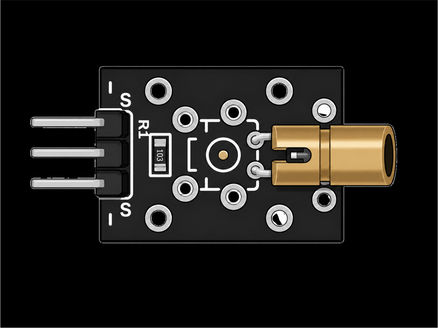
The brass cylinder holds a laser diode and a small lens. The SensorKit lesson's notes give its wavelength as 650 nanometres, a deep red. A laser diode is a close relative of an LED: current flows one way through a junction in the chip and it gives off light. The difference is that the chip's polished ends act as mirrors, so the light bounces back and forth and builds up in step before it escapes in one direction. The lens then gathers it into a narrow beam.
The board around it adds a resistor (R1) and a three-pin header, so you can drive the laser straight from a pin the way the course does. S switches it, − is ground, and the middle pin goes to 5V.
Wiring, and the mistake that kills it
| KY-008 pin | HERO Board pin | What it does |
|---|---|---|
| S | D4 | HIGH turns the laser on, LOW turns it off |
| Middle pin | 5V | Power |
| − | GND | Ground |
Pins from the SensorKit lesson's code. The filmed walkthrough drives S from D13, from an earlier version of the sketch; either works if the code matches.
Check the power pins twice before you plug in USB. In the KY-008 walkthrough, the instructor admits he fried one of these modules while recording by getting ground and positive the wrong way round. Laser diodes are far less forgiving of reversed power than the ordinary LEDs in the kit, and a dead one doesn't come back.
D4 isn't a special pin, and that's the point. The lesson keeps the laser off D0 and D1 (USB serial), D2 and D3 (interrupts), the PWM pins and the SPI pins, because a part that's only ever on or off doesn't need any of them.
The code: Blink, with a laser
const int KY_008_PIN = 4;   // the module's S pin

void setup() {
  pinMode(KY_008_PIN, OUTPUT);
}

void loop() {
  digitalWrite(KY_008_PIN, HIGH);  // laser on
  delay(1000);                     // for one second
  digitalWrite(KY_008_PIN, LOW);   // laser off
  delay(1000);                     // for one second
}If you've run Blink, you already know this sketch. pinMode() makes D4 an output, digitalWrite(HIGH) puts 5 V on S and the dot appears, and LOW takes it away. Change the two delays and you change the rhythm: 100 and 900 gives a short flash once a second. Anything that's on or off, from this laser to the relay, is driven exactly this way.
Build a laser tripwire
The kit already holds the other half of the classic laser build: the KY-018 photoresistor. Aim the dot onto it across a doorway or the opening of a box and its reading jumps. When something crosses the beam, the reading falls back, and your code notices. Add the KY-012 active buzzer and you have an alarm.
const int LASER_PIN = 4;    // KY-008 S
const int LIGHT_PIN = A0;   // KY-018 S
const int BUZZER_PIN = 8;   // KY-012 S

int baseline;   // the light reading with the beam on the sensor

void setup() {
  pinMode(LASER_PIN, OUTPUT);
  pinMode(BUZZER_PIN, OUTPUT);
  Serial.begin(115200);
  digitalWrite(LASER_PIN, HIGH);    // beam on
  delay(500);                       // let the reading settle
  baseline = analogRead(LIGHT_PIN);
}

void loop() {
  int reading = analogRead(LIGHT_PIN);
  bool broken = abs(reading - baseline) > 100;   // the beam is blocked
  digitalWrite(BUZZER_PIN, broken ? HIGH : LOW);
  Serial.println(reading);
  delay(20);
}Rather than guess a threshold, the sketch measures the sensor with the beam on it when it starts, then sounds the buzzer whenever the reading moves more than 100 away from that. So aim first, then press the board's reset button. If it goes off by itself, raise 100; if a hand passing through doesn't set it off, lower it. The Serial Monitor (115200 baud) shows the readings while you tune.
- Shade the photoresistor from room light with a short paper tube, so the laser makes most of the difference.
- Mount the laser low and pointing along a wall or across a box, never at head height where someone could walk into the beam with their eyes.
- Read more about the sensor side in the photoresistor article, and the buzzer side on the KY-012 page.
When it doesn't work
- No dot at all. Check S is on the pin your code drives (the video uses D13, the lesson's code D4), then check the middle pin is on 5V and − on GND.
- It worked, then stopped after rewiring. If the power pins were reversed even briefly, the diode may be dead, as the instructor found.
- The tripwire never fires. Watch the readings in the Serial Monitor as you block the beam. If they barely move, room light is swamping the sensor: shade it, or move the laser closer.
- The tripwire fires on its own. Lamps, sunlight and people's shadows change the light level. Raise the threshold, or re-measure the baseline by pressing reset.
The KY-008 is also a part in the free browser simulator, so you can wire it and run the blink sketch with no beam to worry about. For the rest of the modules in the case, see the 37-in-1 sensor kit guide.
37-in-1 Sensor Kit: The laser, the photoresistor and the active buzzer for a tripwire, plus 34 more modules and the free SensorKit course.
HERO Board: The Uno-compatible board every SensorKit walkthrough is filmed on, with its USB cable.
Questions
Is the KY-008 laser safe?
It's safe to use with one firm rule: never point it at eyes, people's or animals', and never look into the tube. Aim it at walls, sensors and the floor, keep it below head height, and switch it off when you're done. The kit is for ages 12 and up, as printed on the box.
What wavelength is the KY-008 laser?
650 nanometres, a red laser, according to the SensorKit lesson's notes.
Do I need a resistor with the KY-008?
No. The module carries its own resistor, and the SensorKit course wires S straight to a digital pin. What you must get right is the power: the middle pin to 5V and − to GND, never reversed.
Why did my KY-008 stop working?
The most common cause is reversed power. Laser diodes don't tolerate it, and the walkthrough's instructor lost a module the same way. Check that S is on the pin your code drives before you assume it's dead.