KY-001 temperature sensor module (DS18B20): wiring and code
Updated
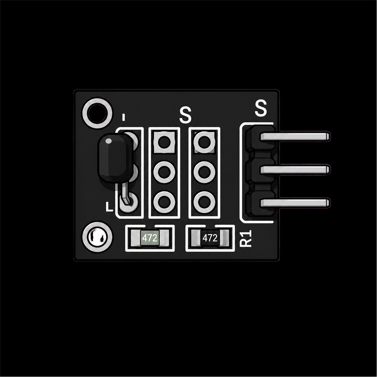
The KY-001 is the most accurate thermometer in the 37-in-1 sensor kit. The black three-legged part on it looks like a transistor, but it's a DS18B20: a whole digital thermometer in one tiny package. It measures the temperature itself and sends it to your board as a number, over a single wire.
That last part is what makes it different from every other sensor in the case. There's no voltage to convert and nothing to calibrate, but you do need a library and a little protocol. Here's how it works, how to wire it to the HERO Board, and the course's code explained.
What's on the board
- The DS18B20. The black part with the flat face. Inside are a temperature sensor, a converter that turns the reading into a 9 to 12-bit number, and a small memory called the scratchpad, where the latest reading waits for your board to collect it.
- A 4.7 kΩ pull-up resistor (marked 472). The data line has to be held at 5 V between messages, and the module brings its own resistor for that, so the S pin wires straight to your board.
- A 3-pin header: S for data, the middle pin for 5 V, and the minus pin for ground.
The course's notes give the DS18B20's range as -55 to +125 °C, accurate to ±0.5 °C between -10 and +85 °C. At its full 12-bit resolution each step is 1/16 of a degree, which is why the code multiplies the raw reading by 0.0625.
How 1-Wire works
The DS18B20 talks over 1-Wire: one data line plus ground, shared by every device on it. Your board runs the conversation. It pulls the line low for set lengths of time to send bits, then lets go and lets the sensor pull it low to answer. Those timings are measured in millionths of a second, and the OneWire library handles them, so your sketch only deals in bytes.
Every DS18B20 has a unique 64-bit address set at the factory: an 8-bit family code (0x28 for the DS18B20, 0x10 for its older cousin the DS18S20), a 48-bit serial number, and an 8-bit checksum. Because each one answers only to its own address, several sensors can share the same pin and you read them one at a time. The course's sketch is built for that: it finds every sensor on the wire at start-up and prints one column per sensor.
A reading takes three steps. Tell the sensor to measure (command 0x44), wait while it converts, then ask for its scratchpad (command 0xBE) and read nine bytes back. The first two bytes are the temperature and the ninth is a checksum, so a reading garbled by a loose wire gets thrown away instead of printed. At 12 bits a conversion can take up to three quarters of a second, so plan on about one reading a second per sensor.
Sending the temperature as a number has a bonus: a longer wire doesn't shift the reading the way it can shift an analog voltage.
Wiring the KY-001 to the HERO Board
| KY-001 pin | HERO Board | What it carries |
|---|---|---|
| S | Pin 4 | 1-Wire data |
| Middle (+) | 5V | Power |
| Minus (-) | GND | Ground |
Why pin 4? The course's code explains the choice. Pins 0 and 1 carry the USB serial link, 2 and 3 are worth saving for interrupts, 13 drives the built-in LED, 5, 6, 9, 10 and 11 are best kept for PWM, and 11 and 12 also carry SPI. That leaves 4, 7 and 8 as the pins least likely to clash with anything you add later. In the walkthrough video the signal goes to pin 10 instead. Either works, as long as the number in KY_001_PIN matches the wire.
The code
Install the OneWire library first: in the Arduino IDE open Sketch > Include Library > Manage Libraries, search for OneWire and install it. This is the course's sketch with the debug printing and comment banners taken out.
#include <OneWire.h>

const uint8_t KY_001_PIN = 4;   // the module's S pin
const int MAX_DS_DEVICES = 5;   // room for up to five sensors on one pin

OneWire ds(KY_001_PIN);
byte ds_addresses[MAX_DS_DEVICES][8];   // each sensor's 64-bit address
int ds_count = 0;

void setup() {
  Serial.begin(9600);

  // Find every DS18x20 on the wire and keep its address
  for (int i = 0; i < MAX_DS_DEVICES; i++) {
    if (!ds.search(ds_addresses[ds_count])) break;      // no more devices
    byte *addr = ds_addresses[ds_count];
    if (OneWire::crc8(addr, 7) != addr[7]) break;       // address garbled
    if (addr[0] == 0x10 || addr[0] == 0x28) ds_count++; // DS18S20 or DS18B20
  }
  Serial.print("Found ");
  Serial.print(ds_count);
  Serial.println(" devices.");
}

void loop() {
  byte data[9];

  for (int i = 0; i < ds_count; i++) {
    if (i > 0) Serial.print(", ");   // one column per sensor

    ds.reset();
    ds.select(ds_addresses[i]);
    ds.write(0x44, false);           // start a conversion (the module has its own 5 V)
    while (!ds.read_bit()) {}        // the sensor answers 0 until it's done

    ds.reset();
    ds.select(ds_addresses[i]);
    ds.write(0xBE);                  // read the scratchpad: 9 bytes
    for (int j = 0; j < 9; j++) data[j] = ds.read();
    if (OneWire::crc8(data, 8) != data[8]) return;   // garbled: try again

    int16_t raw = (data[1] << 8) | data[0];
    Serial.print(raw * 0.0625);      // 1/16 of a degree per step
  }
  Serial.println();
}Two lines do the clever work. ds.search() walks the bus and fills in one address per call, so the setup loop collects up to five sensors and stops at the first address whose checksum fails. And while (!ds.read_bit()) {} is the wait: while a conversion runs the sensor answers 0, and it answers 1 the moment the reading is ready.
Open the Serial Monitor at 9600 baud and you'll see one temperature per line, in °C. The walkthrough read about 24 at room temperature. A fingertip on the sensor pushes the number up within seconds, and blowing on it brings it back down. With two or more sensors, open the Serial Plotter instead: each column becomes its own line on the graph.
The shorter way: DallasTemperature
In the walkthrough the instructor also installs the DallasTemperature library. It sits on top of OneWire and handles the addresses and the math for you. This version isn't from the course, but it reads the same sensor on the same pin:
#include <OneWire.h>
#include <DallasTemperature.h>

OneWire oneWire(4);                  // the module's S pin
DallasTemperature sensors(&oneWire);

void setup() {
  Serial.begin(9600);
  sensors.begin();
}

void loop() {
  sensors.requestTemperatures();     // every sensor on the pin measures
  float c = sensors.getTempCByIndex(0);
  if (c == DEVICE_DISCONNECTED_C) {
    Serial.println("No sensor found");
  } else {
    Serial.println(c);
  }
  delay(1000);
}getTempCByIndex(0) reads the first sensor the library found, and getTempFByIndex(0) gives the same reading in Fahrenheit. If nothing answers, the library returns -127, which is what the sketch checks for.
KY-001, KY-015 or KY-028: which temperature module?
The kit has three modules that react to heat, and they aren't interchangeable.
| KY-001 | KY-015 | KY-028 | |
|---|---|---|---|
| Sensor | DS18B20 digital thermometer | DHT11 | Thermistor and comparator |
| Gives you | Degrees, as a number | Degrees and humidity, in whole numbers | A raw level, plus on/off at a set point |
| Range | -55 to +125 °C | 0 to 50 °C, 20 to 90 % humidity | Not calibrated |
| Library | OneWire | DHT sensor library | None |
| Best for | Accurate readings, several sensors on one pin | Humidity | A thermostat-style trip point |
Use the KY-001 when the number matters. The KY-015 is the one to pick for humidity, and the KY-028 is a switch that trips at a temperature you set with a screwdriver, with no math in your code at all.
Common problems
- "Found 0 devices." The S wire isn't on the pin named in
KY_001_PIN, or the module has no power. Check the middle pin goes to 5V and minus to GND. - -127. That's DallasTemperature's way of saying no sensor answered. The same wiring checks apply.
- Exactly 85.00. The DS18B20 starts up holding 85 °C in its scratchpad. Read it before a conversion finishes, or after the power dips, and that's what you get. The course's sketch waits for the conversion to finish, which avoids it.
- Strange characters in the Serial Monitor. The baud rate at the bottom of the monitor has to say 9600 to match
Serial.begin(9600). Here's the fix in full. - The reading lags the room. The sensor measures its own body, so it takes a little while to follow the air around it, and it reads warm for a moment after you've held it.
What to build with it
- Two temperatures at once. Add a second DS18B20 on pin 4 (any DS18B20 shares the wire, including the waterproof probe kind), and the Serial Plotter draws inside and outside together.
- A temperature alarm. Compare the reading with a limit and sound the kit's KY-012 active buzzer when it's crossed.
- A readout. Print the temperature on an OLED display instead of the Serial Monitor.
- A fan that switches itself on. Drive a small fan through the kit's KY-019 relay when the reading passes a limit.
Watch it wired up
The KY-001 is the first walkthrough in the SensorKit course. For the rest of the case, see every module in the 37-in-1 sensor kit. The KY-001 is also a part in the free browser simulator, so you can run both sketches above before you wire the real one.
37-in-1 Sensor Kit: The KY-001 and the rest of the 37 modules in a latching case, with the free SensorKit course: 31 filmed walkthroughs and example code.
HERO Board: The Uno-compatible board the SensorKit walkthroughs are built around, with its USB cable.
Questions
Is the KY-001 a DS18B20?
Yes. The black three-legged part on it is a DS18B20 digital thermometer, and the module adds the 4.7 kΩ pull-up resistor its data line needs.
Which library does the KY-001 need?
OneWire is enough, and it's what the SensorKit course's sketch uses. DallasTemperature, which builds on OneWire, makes the code shorter.
Can I connect more than one DS18B20 to one pin?
Yes. Each one has its own 64-bit address, so several can share a data pin. The course's sketch finds up to five and prints one column for each.
Why does my KY-001 read -127 or 85?
-127 means no sensor answered: check the wiring and the pin number. 85 is the value the chip holds at power-up, read before a conversion finished.